A battery simulation DC power supply is chosen by matching its electrical range and behavior to the battery and device being tested. Voltage, peak current, power, bidirectional operation, transient response, and the required battery model are the core selection criteria.
Unlike a conventional fixed-output supply, a battery simulator is intended to reproduce changing battery conditions during charging and discharging. This can support testing of BMS units, chargers, inverters, portable electronics, and other battery-powered equipment.
Summary: Match voltage, current, and power to the test case. Choose bidirectional operation when the device charges or returns energy. Check transient behavior, battery-model functions, integration interfaces, scalability, and protection features.
What is a battery simulation DC power supply?
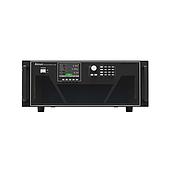
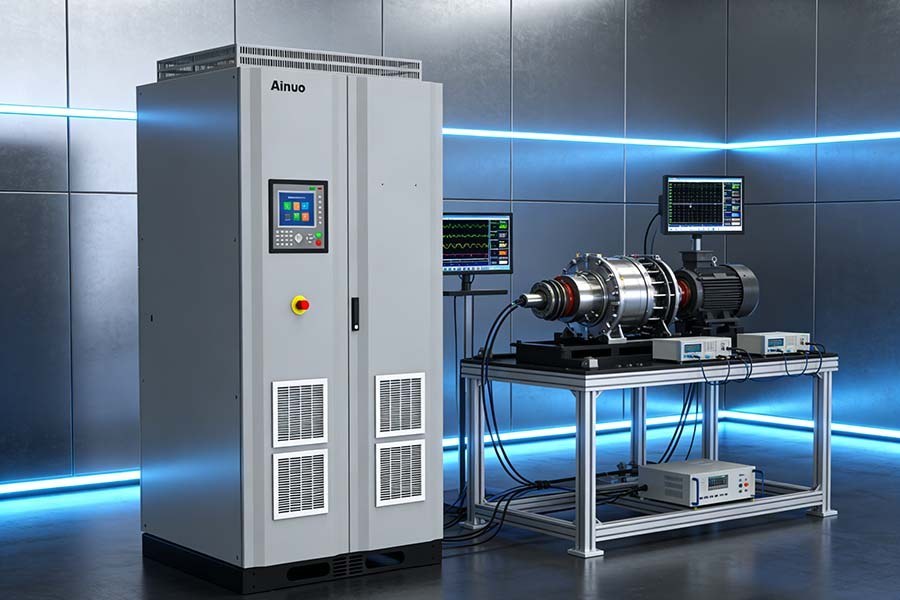
A battery simulation DC power supply is a programmable DC system designed to emulate electrical battery behavior rather than only provide a stable output. Depending on its capabilities, it can represent state-of-charge-related voltage changes, internal-resistance effects, and changing responses to load.
This distinction matters when a device must be evaluated under conditions closer to charge and discharge operation. A regular DC power supply may not reproduce bidirectional energy flow or battery-related voltage behavior.
Why use a battery simulator instead of a physical battery?
A battery simulator can provide repeatable test conditions without waiting through physical battery charge and discharge cycles. It also avoids changes caused by battery aging and enables rapid adjustment of simulated state of charge.
For development work, repeatability can make it easier to compare results across test runs. Simulation may also be used to evaluate conditions such as overvoltage or short-circuit scenarios without relying on a physical battery.
Which voltage, current, and power ratings should be checked first?
Start with the battery’s nominal voltage, the device’s expected operating current, peak current demand, and total power requirement. The selected system must cover these values, including expected transient spikes, rather than only the average load.
| Test application | Selection emphasis described in the source |
|---|---|
| Consumer electronics | Low voltage and current, precision, and response to mobile or pulse loads |
| Electric vehicles | High voltage, high power, fast transients, and regenerative-energy support |
| Renewable energy and ESS | Long-duration cycling, high power, and grid interaction |
| BMS testing | Accurate SOC modeling, fault simulation, and multi-channel support |
The source describes consumer-electronics applications as typically operating in the 3 V to 20 V range, while automotive and EV systems can extend to 1500 V. These examples are application contexts, not universal requirements.
When is bidirectional source-and-sink operation necessary?
Bidirectional operation is necessary when the test setup must both deliver energy to the device and absorb energy returned by it. Sourcing represents battery discharge, while sinking represents battery charging.
This capability is relevant to battery chargers, regenerative braking systems, and power electronics with energy feedback. If returned energy is part of the operating scenario, a source-only supply does not represent the full energy-flow behavior.
Why do transient response and battery modeling matter?
Transient response matters because real loads can change quickly, and batteries do not behave as ideal, unchanging voltage sources. Assess response time, voltage or current slew rate, and stability during rapid load switching.
Battery modeling should be assessed separately from basic output ratings. Useful model elements may include open-circuit-voltage curves, state-of-charge profiles, internal-resistance variation, and aging or degradation effects.
Note: A low average-power requirement does not rule out high transient demand. Evaluate startup, switching, or pulse-load events against the system limits.
How should accuracy, resolution, and regenerative capability be evaluated?
Accuracy and measurement resolution are especially relevant when small changes affect the result, such as in low-power IoT work, semiconductor testing, or battery-efficiency measurements. Review voltage accuracy, current resolution, and measurement precision against the intended test objective.
In a bidirectional setup, absorbed energy may be dissipated as heat or returned to the grid by a regenerative system. Regeneration can be particularly relevant for high-power tests and continuous cycling, where absorbed energy is substantial.
Which controls, integration options, and safety features should be included?
Choose control interfaces and software functions that fit the planned workflow. The source identifies USB, LAN, GPIB, and CAN as possible remote-control interfaces, along with automation support, scripting, test profiles, data logging, and hardware-in-the-loop integration.
Protection functions should be reviewed as part of the test system, not as an afterthought. Relevant features listed in the source include overvoltage, overcurrent, thermal protection, and isolation.
What selection mistakes should be avoided?
Do not treat battery simulation as a simple voltage-and-current matching exercise. Selecting a conventional source-only supply can miss battery behavior, internal resistance, and bidirectional energy flow required by the test.
Also avoid ignoring transient peaks, software and automation needs, or future expansion. A scalable or modular approach may be important when power needs, channel count, or test complexity are expected to grow.
What is a practical selection sequence?
Define the device under test and the battery behavior that must be represented, then establish voltage, current, peak power, and transient requirements. Next, decide whether bidirectional operation, model DC power supply, regeneration, multi-channel capability, or fault simulation is necessary.
- Document the electrical range and load profile.
- Identify charge, discharge, and energy-feedback scenarios.
- Set requirements for SOC, resistance, and aging models where applicable.
- Confirm control interfaces, automation, and data-logging needs.
- Review protection features and options for future expansion.