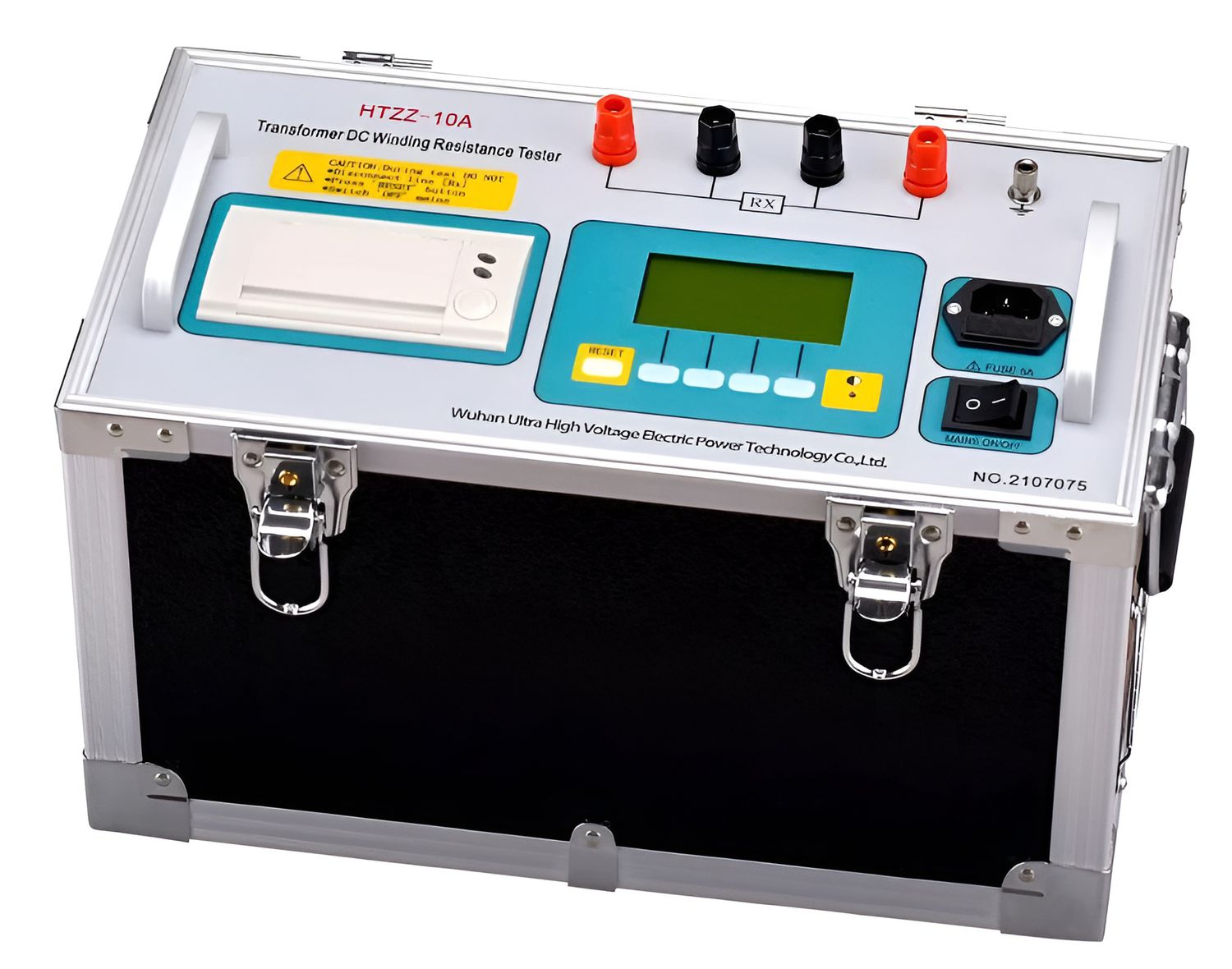
In the production and operation of electrical systems, periodic testing provides a basis for monitoring equipment condition. DC resistance meter is used to measure the resistance of components such as transformer windings, switching contacts, cables, busbars, and motor windings. Measurement results provide important data for identifying abnormal changes at conductive points or internal connections, comparing results between inspections, and evaluating equipment changes over time.
What Is a DC Resistance Meter Used For ?
DC resistance is a parameter that reflects the conductive characteristics of a test element under defined measurement conditions. When the measured value changes abnormally compared with historical data or between equivalent positions, operators have additional information for assessing the condition of connections, conductors, and windings.
DC resistance meters are commonly used for:
Measuring the winding resistance of transformers.
Evaluating contact resistance in switching equipment.
Checking cable terminals, cable connections, and crimped joints.
Measuring the resistance of busbars or motor windings when required by the test procedure.
Low-Resistance Measurement: Test Lead Position Affects the Result
At low resistance levels, the resistance of test leads and contact points can become a significant part of the total measured value. A four-wire Kelvin configuration separates the current path from the voltage-sensing path, reducing the influence of lead resistance on the measurement.
The position of the Sense leads also requires attention. The voltage should be measured as close as possible to the element whose resistance is being determined. If the voltage-sensing points are placed too far from the test object, the resistance of the conductor between these points can be included in the measurement.
This is particularly relevant for busbars, connectors, and contacts with extremely low resistance, where even a small change in lead placement can produce a noticeable difference between two measurements.
Thermoelectric Voltage and Metal Contacts
When the voltage being measured is only in the microvolt or millivolt range, parasitic voltages within the measurement circuit can become significant. One common source is thermoelectric EMF generated at junctions between different metal materials when a temperature difference exists.
A contact point also does not provide an ideal conductive area. Current flows through actual contact regions on the metal surface, while oxide layers or surface films can alter contact characteristics.
Therefore, low-resistance measurements require consideration of both the current path and the location where the measurement voltage is developed, rather than focusing solely on the final displayed value.
Windings Require Time to Reach a Stable State
The windings of transformers, motors, and inductors do not behave like pure resistors. When DC current is applied, magnetic energy builds up in the winding, and the current requires a certain amount of time to reach a stable state.
If the result is recorded too early, the measured value may not represent the winding's steady-state condition. For windings with high inductance, the stabilization time can be considerable.
This characteristic also affects measurement repeatability. Two tests performed on the same winding but recorded at different points in time may produce different results even when the electrical condition of the winding has not changed.
Test Current Directly Affects Winding Temperature
Increasing the test current produces a higher voltage across the resistance being measured, but it also increases power dissipation:
P = I²R
As current increases, the heat generated in the winding increases with the square of the current. Since conductor resistance depends on temperature, the measurement process itself can change the condition of the test object.
For this reason, the test current should be selected according to the size, resistance, and thermal characteristics of the test object. When monitoring equipment over multiple inspections, maintaining similar test-current conditions also improves the comparability of the measurement data.
Transformer Winding Measurements Require Attention to Residual Magnetism
A transformer winding resistance meter applies DC current through the transformer winding, which can leave residual magnetism in the magnetic core. This condition may remain after the measurement has been completed and can affect the transformer's magnetic characteristics during subsequent energization.
Therefore, measuring transformer winding resistance does not end when the resistance value has been recorded. Current interruption, energy discharge, and demagnetization should be handled appropriately for the equipment under test.
This is an important distinction between measuring the resistance of a conventional component and measuring a system containing a highly inductive element.
Measurement Values Should Be Recorded Alongside Test Conditions
An effective data management system should store measurement results together with relevant information such as the measurement location, temperature, test current, measurement time, and operating conditions. When these parameters are maintained consistently, changes in resistance over multiple test cycles can provide useful information about the condition of current paths and windings.
The four-wire configuration, test current, ability to handle inductive loads, stabilization time, capability for offset-voltage compensation, and data-recording method all affect the practical value of the instrument.
For high-current paths, contacts, busbars, or highly inductive windings, a low-resistance meter is generally more suitable than a conventional resistance meter.
An increase in temperature can cause conductor resistance to rise, while a decrease in temperature can reduce resistance. Recording and compensating for temperature when necessary makes comparisons between measurement results more meaningful.
When selecting a miliom meter, determine in advance the resistance range to be measured, the inductive characteristics of the load, the required test current, and how the measurement data will be used afterward.