Miliom meter helping identify abnormalities associated with connections, contact quality, and consistency between equivalent components. For transformers, switchgear, cables, and systems with high-current connections, measurement data can provide useful information for monitoring equipment condition over time.
What Is DC Resistance Measurement ?
DC resistance measurement, also known as DC resistance testing, uses a low-voltage direct current source to determine the resistance of a winding or conductor. The primary purpose is to verify the continuity of the electrical path and identify potential problems with electrical connections.
In practice, the measured resistance does not depend solely on the conductive material itself. It is also affected by terminals, bolts, solder joints, and contact interfaces within the circuit. If a connection is loose, oxidized, or has insufficient contact area, its local resistance may increase. When carrying current, such a point can generate excessive heat and affect the reliability of the equipment.
Operating Principle of a DC Resistance Meter
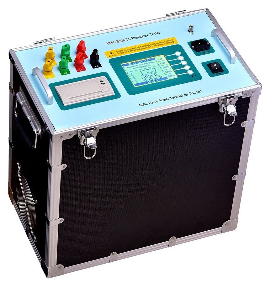
A DC resistance meter typically applies a controlled current through the device under test while measuring the voltage across it. The resistance is then determined from the measured current and voltage.
This method is particularly suitable for measuring the low resistance of conductors, windings, and electrical contacts.
During measurement, the reading should be allowed to stabilize before the result is recorded. This is especially important when testing windings, where the measurement may require more time to stabilize than a short conductor.
Recording the value too early or changing the connections during the test can reduce the reliability of comparisons between measurements.
Factors Affecting Measurement Results
Conductor Material and Cross-Section
Resistance depends on the material and cross-sectional area of the conductor. Different materials have different resistivities, while, under the same conditions, a conductor with a larger cross-sectional area generally has lower resistance.
For this reason, measurements should primarily be compared between components with equivalent construction and operating conditions.
Temperature
Temperature is an important factor because the resistance of metallic conductors changes with temperature. When equipment has recently been operating or remains hot, the measured resistance may differ from the value obtained under cooler conditions.
The temperature at the time of measurement should therefore be recorded. Maintaining consistent test conditions between measurements also makes trend analysis more meaningful.
Connection Quality
Bolted connections, terminals, solder joints, and electrical contacts require particular attention. Oxidation, loose connections, or poor contact surfaces can increase local resistance.
This is why a DC resistance meter is often used together with mechanical inspection and visual examination of connection points.
Conductor Length and Test Conditions
A longer conductive path generally has higher resistance. In addition, contact surface cleanliness, test lead connections, and environmental conditions can affect measurement stability.
A consistent measurement procedure should therefore be maintained so that results from different inspections can be compared reliably.
Applications in Electrical Equipment Testing
DC resistance meters are used for various applications involving windings or current-carrying electrical paths. Depending on the equipment, the purpose of the measurement may differ.
Transformers: Measuring winding resistance, comparing corresponding phases or winding sections, and evaluating the condition of winding connections.
Switchgear: Measuring contact resistance in circuit breakers, disconnectors, and related switching components.
Cables and cable joints: Evaluating the condition of terminals, cable ends, and connection points along the cable route.
Grounding systems: Assessing electrical connections between grounding conductors and grounding components within the scope of the conductive path being tested.
Busbars and generator windings: Identifying abnormal resistance differences at high-current conductive paths and connection points.
For equipment with similar structures across multiple phases, comparing measurements between phases can provide useful diagnostic information. A significant difference from corresponding phases should be assessed together with temperature, connection configuration, and operating history rather than being judged solely from a single measurement.
How to Perform Effective DC Resistance Testing
The test should first be performed according to the applicable safety procedures and the manufacturer's operating instructions. The equipment under test must be in an appropriate condition, and the operator should verify all connections before starting the measurement. The working area should also be dry and suitable for electrical testing.
Measurements should be performed with the temperature clearly recorded. When comparing results from different inspections, testing equipment after it has cooled to a similar condition can improve consistency.
For multi-phase systems or equipment with several equivalent components, measurements should be taken at corresponding points and all results should be properly recorded. Rather than evaluating a single resistance value, monitoring changes across successive maintenance inspections can help identify abnormal trends at an earlier stage.
A low-resistance meter is an important tool for this type of testing, but measurement results are more meaningful when considered together with the actual equipment condition, test temperature, connection configuration, and a consistent measurement procedure. This approach provides a stronger basis for maintenance decisions and helps maintain the reliability of electrical connections.
Frequently Asked Questions
Why is the measured resistance different from the expected value ?
The difference may be caused by temperature, contact surface condition, oxidation, connection quality, or inconsistent test conditions. Before evaluating the result, check the test lead connections, measurement timing, and equipment temperature.
How is DC resistance measurement different from AC resistance measurement ?
Low resistance tester focuses on the resistance of an electrical path or winding when a direct current is applied. When measurements are performed in an AC circuit, additional characteristics associated with AC operation may need to be considered depending on the purpose of the test.
Should a conclusion be based on a single measurement ?
Generally, no. Comparing measurements between phases, reviewing previous results obtained under similar conditions, and inspecting connection points can provide a more reliable basis for assessing equipment condition.