Motor Jerking and Inverter Displaying Encoder Fault: What Are the Causes?
Most pulse loss cases fall into four root cause categories: electromagnetic interference (EMI) along the signal line, physical cable or connector damage, dirty or failed encoder optical/magnetic heads, or faulty signal input circuits on the inverter/PLC side. Each category presents unique symptoms that must be correctly identified prior to dismantling equipment for repair.
Why Are Encoder Signal Cables Susceptible to Interference and Missing Pulses?
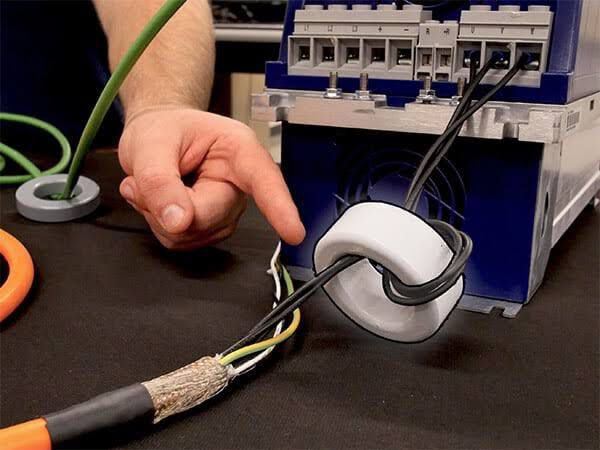
Encoder signals consist of very low-voltage electrical pulses that are easily affected by magnetic fields generated by nearby high-power motor cables. Routing signal cables in shared trays or conduits with motor power lines introduces false pulses over genuine ones or causes complete pulse loss during heavy motor loads. This issue is among the hardest to detect visually, typically manifesting only when the motor operates at high speeds or under sudden load changes.
Fundamental preventive measures include routing signal cables completely separate from motor power cables, utilizing shielded encoder cables, and properly grounding the shield according to technical standards.
How to Detect Internal Wire Breaks or Loose Connectors in Encoder Cables?
Feedback signal cables connecting encoders to inverters often undergo repeated bending during machine motion. Over time, internal conductors may fracture inside the outer jacket while appearing intact externally. Loose connectors resulting from machine vibration or improper installation cause similar intermittent signal loss.
The simplest diagnostic method is performing continuity tests on each encoder wire using a multimeter while gently flexing the cable along its length to detect internal fractures or intermittent contact points.
How Do Dirty Code Discs and Damaged Optical Sensor Heads Affect Encoder Signals?
Encoders house an internal code disc rotating with the motor shaft, alongside optical or magnetic sensors reading disc graduations to generate pulses. Dust, grease, or oil accumulation on the disc or sensor weakens or interrupts signal readings, mimicking cable-induced pulse loss. Age-related sensor degradation yields similar results, which remain difficult to distinguish visually without disassembling the encoder for inspection.
How Do Hardware Faults in Inverters, PLCs, or PG Cards Cause Missing Pulses?
Even when an encoder emits correct pulses, component failures within the receiving circuitry on the inverter, PLC, or PG card lead to inaccurate readings or signal loss. This scenario causes frequent misdiagnoses, with technicians often misattributing the issue to the encoder when the root cause lies within the controller interface.
How to Test and Troubleshoot Encoder Signal Pulse Loss
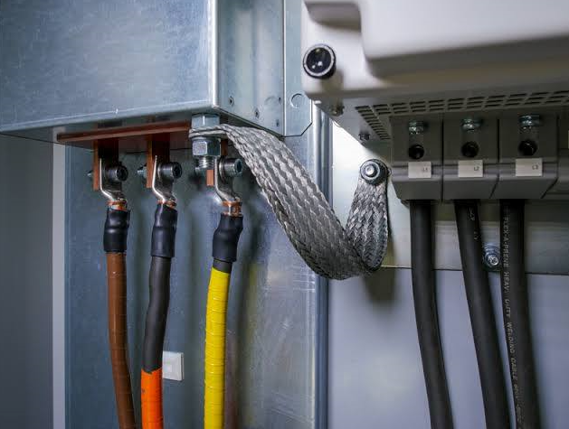
- Test encoder cable continuity and thoroughly clean all contact points and connectors.
- Verify that cable shield integrity is maintained and that grounding connections are properly bonded without loose joints.
- Use an oscilloscope to directly measure output pulses across channels A, B, and Z, comparing observed waveforms against standard manufacturer specifications.
- In cases of internal hardware failures involving the code disc or optical sensor, contact specialized repair services or replace the encoder. Do not attempt unauthorized disassembly without proper technical expertise.
Explore related products at EMIN: Tachometers & Pulse Counters