2-port shunt-through impedance measurement uses a gain trace to read impedance in Ohms during a frequency sweep. In the documented Bode 100 workflow, the setup is configured in Gain/Phase mode, calibrated with a Thru procedure, and evaluated on a logarithmic scale.
For an inductive region of the trace, inductance can be calculated from impedance and frequency using L = Z/(2πf). The source identifies a +1 slope, equivalent to +20 dB per decade, as the point to use for this calculation.
Summary: Configure a frequency sweep in Gain/Phase mode. Connect Ch1 to the internal reference and terminate Ch2 in 50 Ohms. Run Thru calibration for both User Calibration and Probe Calibration. Use a +1 slope region to calculate inductance from impedance and frequency.
What is a 2-port shunt-through impedance measurement?
A 2-port shunt-through measurement is a method for measuring impedance with two ports while displaying the magnitude of the gain trace in Ohms. It supports reading the impedance curve across a selected frequency range rather than at only one frequency.
The documented example applies the method to a 2 mOhm resistor. Its sweep spans from 1 kHz to 40 MHz, illustrating how very low resistance can be examined over a broad logarithmic frequency range.
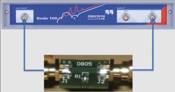
How should the Bode 100 be configured for this measurement?
Start by selecting Frequency Sweep. In the Device Configuration, select Gain/Phase, connect Ch1 to the internal reference, and terminate Ch2 into 50 Ohms.
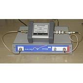
These settings define the documented configuration used to make the gain trace represent impedance in Ohms. The connection arrangement and a 1 Ohm calibrator are shown in the supplied setup illustration.
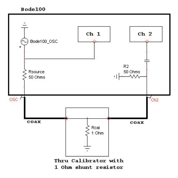
Which calibration steps are required before sweeping?
Perform a Thru calibration for both User Calibration and Probe Calibration before running the measurement sweep. The source presents these two calibration actions as part of the required procedure.
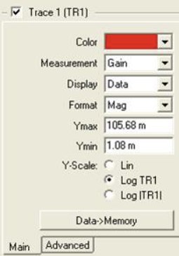
After calibration, run the logarithmic sweep and read Trace 1 on a logarithmic scale. Keeping the sweep and trace scale logarithmic makes it possible to identify the slope behavior used for the inductance calculation.
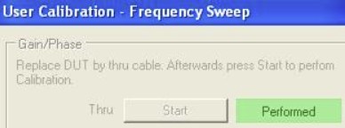
How is impedance read from the logarithmic sweep?
Read Trace 1 on a logarithmic scale after the sweep is complete. In the documented 2 mOhm resistor example, the measured value was 1.8 mOhms over the stated test arrangement and frequency span.
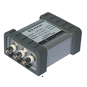
This result is specific to the example and should not be treated as a general correction factor for other components or setups. The source also states that a J2102A Common Mode Transformer was used to remove ground-loop effects in that measurement.
Note: The 1.8 mOhm reading is the reported result for one 2 mOhm resistor example. It does not establish that all 2 mOhm resistors will measure at the same value.
How can inductance be calculated from an impedance trace?
Choose a point on the curve where the slope is +1, identified in the source as +20 dB/decade. This slope represents an inductive impedance region, allowing inductance to be calculated with L = Z/(2πf).
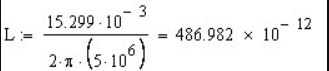
Use the impedance value Z and the frequency f from that selected point in the formula. For the documented 2 mOhm resistor example, the calculated inductance was about 487 pH.
| Measurement item | Documented value or setting |
|---|---|
| Example component | 2 mOhm resistor |
| Sweep range | 1 kHz to 40 MHz |
| Reported resistance reading | 1.8 mOhms |
| Inductive slope selection | +1, or +20 dB/decade |
| Calculated inductance | About 487 pH |
When is the +1 slope criterion useful?
The +1 slope criterion is useful when the goal is to estimate inductance from a measured impedance curve. It provides the condition stated in the source for treating the selected portion of the trace as inductive.
It should be applied to a point that actually shows the specified slope. The calculation depends on the impedance and frequency at that chosen point, so the curve selection is part of the measurement interpretation.