Declining IC performance and chronic respiratory problems among R&D engineers rarely occur immediately. Instead, they accumulate gradually with every solder joint made on surface-mount components. Most damage in modern electronics laboratories stems from two concurrent hazards: electrostatic leakage currents that can rupture the oxide layers of integrated circuits, and organic toxins contained in soldering fumes. Addressing these two risks requires a systematic approach to surface physics and airflow dynamics rather than relying solely on individual pieces of equipment.
The Silent Destruction of ICs Caused by Low-Voltage Leakage Currents
Most engineers focus on preventing high-voltage electrostatic shocks of thousands of volts (kV) that can generate visible sparks. However, the actual danger can come from microscopic electrostatic discharges at voltages as low as 10 V to 100 V. Extremely small field-effect transistor gate structures and thin-film components can be highly vulnerable to breakdown at these voltage levels, resulting in two main types of failure.
The first is catastrophic failure, in which the component dies immediately on the test bench. Although this type of failure can be costly because the component must be replaced, it is relatively easy to detect. More dangerous is latent failure, which occurs when the silicon dioxide (SiO₂) insulation layer is only slightly damaged. The component may still pass initial testing but fail unexpectedly after several weeks of operation at the customer's site.
Notably, the main source of electrostatic hazards does not come solely from the operator's body. It can also originate from a soldering iron with electrical leakage or inadequate grounding. When a heated soldering tip comes into contact with the pads of a surface-mount component, even a very small potential difference from an electronic component soldering machine that does not meet ESD safety requirements can generate a damaging surge current capable of compromising the extremely thin structures inside an integrated circuit.
The Toxic Chemical Composition of Soldering Fumes from Surface-Mount Components
In addition to the risk of damage to microelectronic structures caused by leakage currents, heat transfer at the soldering tip (300°C–400°C) can vaporize flux and encapsulating resins, generating fumes that pose a direct risk to operators. Soldering fumes are not simply carbon particles. They are a mixture of airborne particles containing organic contaminants such as abietic acid, formaldehyde, acetaldehyde, and volatile organic compounds (VOCs) that can irritate the respiratory system.
At the same time, high temperatures can release fine particles of heavy metals such as lead (Pb), tin (Sn), and silver (Ag), with particle sizes below 2.5 μm (PM2.5). When inhaled, these particles can reach the alveoli, enter the bloodstream, and accumulate in the body over time. Using a conventional cooling fan or exhaust fan merely disperses these fumes throughout the laboratory, exposing people in the surrounding area to passive contamination.
ESD Control Through Impedance Management
To effectively prevent electrostatic leakage currents from damaging sensitive components, laboratories need to establish a closed-loop equipotential bonding and grounding system in accordance with applicable technical standards and supported by dedicated equipment.
The first link in the chain is controlling the equipment used during component handling. An industrial-grade soldering machine should have a grounding impedance of less than 1 Ω from the soldering tip to the common grounding point, ensuring that the leakage voltage measured at the tip remains below 2 mV RMS.
For insulating surfaces such as plastic housings, microscope bodies, and component trays—where grounding wires cannot provide effective charge dissipation—installing static eliminator is essential. The device generates both positive and negative ions to neutralize residual electrostatic charges, particularly in dry cleanroom environments. Operators should also use a grounded wrist strap incorporating a 1 MΩ resistor. This allows electrostatic charges from the body to be continuously discharged to the grounding system while providing protection against hazardous mains leakage currents.
Source Capture of Soldering Fumes Through a Three-Stage Filtration System
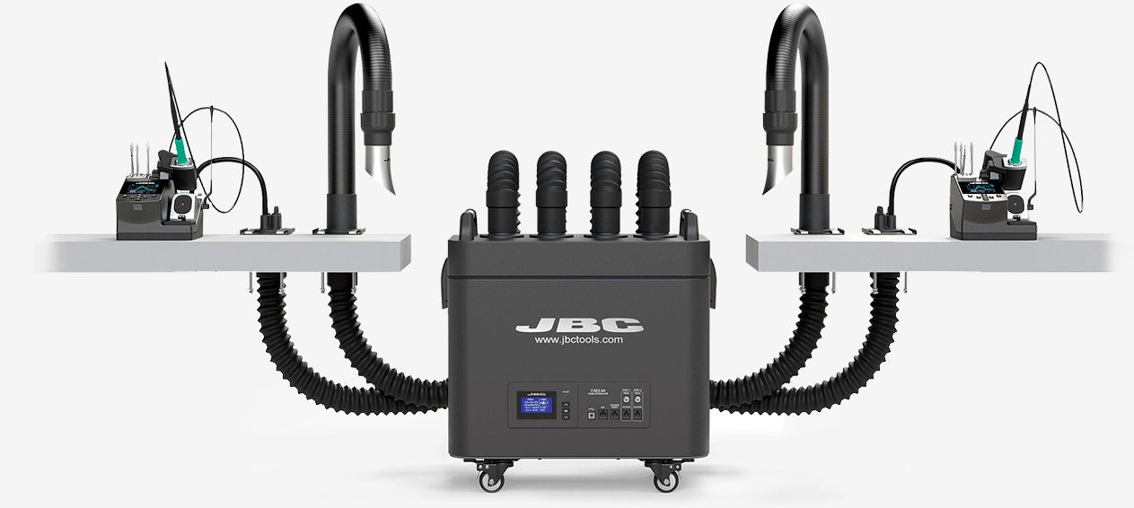
Controlling hazardous fumes requires capturing them at the source before they rise into the technician's breathing zone. A dedicated solder fume extractor can collect contaminated air and direct it through a closed three-stage filtration system.
First, the airflow passes through the extractor's pre-filter, which captures larger dust particles and condensed resin droplets, preventing the downstream filters from becoming prematurely clogged. The contaminated air then passes through a high-efficiency air filter. This stage captures 99.97% of particles with a diameter of 0.3 μm, effectively removing lead particles and other heavy-metal particulates. The final stage contains high-density activated carbon, which adsorbs volatile organic compounds and chemical odors.
With a closed-loop treatment process using a solder fume extractor, the treated air can reach the required cleanliness level and be recirculated directly into the workspace without losing conditioned air from the laboratory.
Maintaining System Stability Through Routine Operation and Inspection
Once the laboratory is equipped with ESD protection infrastructure, dedicated soldering equipment, and a fume filtration system, long-term operational effectiveness depends on regular inspection and maintenance to prevent equipment performance from deteriorating over time.
Technicians should use an ESD meter, electric field meter, or surface resistance meter to periodically check the surface voltage of rubber ESD mats, the conductivity of ESD footwear, and wrist straps before each work shift. These measurements help identify early deterioration in the ability of ESD materials to dissipate electrostatic charges before an IC breakdown occurs.
For solder fume extractors, saturated filters can reduce extraction airflow, meaning the volume of air moved per minute. The pre-filter should generally be replaced every 1–2 months, while high-efficiency and carbon filters should be replaced every 6–12 months, depending on the frequency of soldering operations. In parallel, ionizers should be cleaned regularly, particularly around the ion-emitting pins, to maintain accurate ion balance.
In addition, switching to lead-free SAC305 solder alloy (Sn96.5/Ag3.0/Cu0.5), combined with low-emission synthetic fluxes designed to minimize VOC generation, can help reduce the release of hazardous substances at the source.