How Water Hammer Damages Pressure Gauges & How to Protect Pipeline Measurement Points
Demystifying hydraulic shock, identifying early signs of mechanical failure, and guiding the selection of gauges and protective accessories engineered to withstand surge pressure in industrial systems.
1. What Is Water Hammer and Why Does Stopping Flow Create Extreme Pressure Spikes?
Fluid flowing through a pipe carries substantial kinetic energy. When a valve closes rapidly, a pump trips unexpectedly, a check valve slams shut, or a pump starts up in an unfilled pipe, the flow is abruptly stopped or redirected within milliseconds. This kinetic energy does not vanish; instead, it converts into a high-magnitude pressure wave traveling back and forth along the pipeline between reflection points.
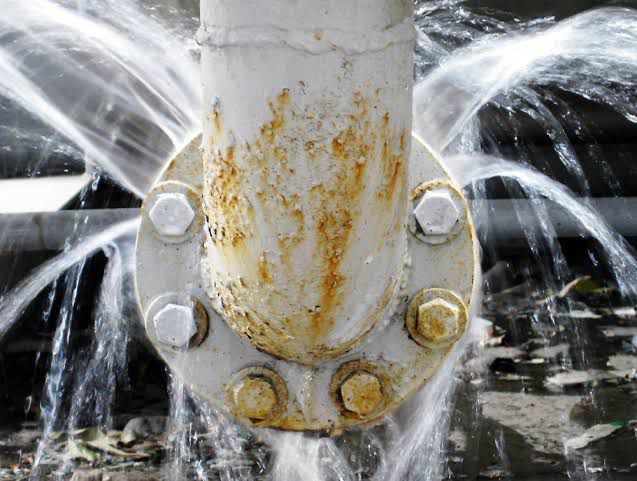
The pressure surge magnitude can be estimated using the Joukowsky equation: pressure increase equals fluid density multiplied by acoustic wave speed and velocity reduction. For water flowing in steel pipes, every 1 m/s of velocity abruptly stopped can trigger a pressure spike ranging from several bar to well over 10 bar.
- Pipe Material: Plastic piping exhibits lower wave propagation speeds than steel, resulting in lower pressure surge peaks.
- Valve Closure Speed: Faster valve closures generate higher pressure spikes; closing a valve slowly relative to the wave reflection travel time significantly mitigates peak pressure spikes.
Consequently, pressure surge levels vary across individual piping systems, making it impossible to apply a single universal value to all pipelines.
2. Which Mechanical Parts of a Pressure Gauge Are Damaged by Water Hammer?
Mechanical dial gauges operate via a Bourdon tube—a thin-walled curved or spiral metal tube that straightens under pressure to rotate the pointer gear movement. When a water hammer surge occurs, shock waves strike four critical mechanical failure points:
Stretched beyond its elastic limit, resulting in permanent deformation or cracking. The most evident sign is the pointer failing to return to 0 bar after venting system pressure.
Continuous shock forces cause rapid gear tooth wear, jamming, or breakage. Pointers driven past full scale bend or snap against the limit stop pin.
High-amplitude acoustic shock waves and case distortion cause cracking or shattering of the protective front glass window.
Shock loads loosen joint threads and degrade gaskets, resulting in process fluid leaks right at the gauge connection stem.
Water hammer also inflicts cumulative damage: repeated small surges induce material fatigue, leading to gauge failure within weeks even without a single massive catastrophic pressure surge.
Key Indicators of Water Hammer in Your System: Metallic thudding sounds during valve operation or pump shutdown, noticeable pipe vibration surges, rapid pointer flutter during valve actuation, zero-point shift, or recurring thread leaks after installing replacement gauges.
3. How to Select the Proper Gauge Scale Range to Withstand Pressure Surges?
Selecting an appropriate full-scale range is the first line of defense and the most cost-effective safeguard. Per EN 837 standards, maximum operating pressure guidelines recommend:
- Steady Load: Should not exceed 75% of the full-scale value.
- Fluctuating / Dynamic Load: Should not exceed 66% of the full-scale value.
- Short-Term Overpressure Limit: Specific models withstand 15% to 25% overpressure beyond full scale for a maximum duration of 15 minutes.
Standard Sizing Rule: For a system operating at 10 bar that experiences frequent valve closures, select a full-scale range significantly higher than the working pressure (e.g., 16 bar to 25 bar) rather than a tight 10 bar range. However, if peak water hammer pressures exceed all safety margins, oversizing the gauge scale alone cannot replace surge mitigation at the source.
4. How Liquid-Filled Gauges Protect Internal Movements & Can They Stop Water Hammer?
Filling a gauge housing with dampening fluid (Glycerine or Silicone Oil) stabilizes the pointer, dampens mechanical vibration, and lubricates internal gear movements against dynamic pressure loads.
- Standard: EN 837-1 / ASME B40.100
- Wetted Parts: Full Stainless Steel
- Dial Sizes: 63, 100, 160 mm
- Ranges: 0...0.6 bar up to 0...1600 bar
- Pre-filled with Glycerine / Silicone Oil
- Engineered for dynamic loads & high vibration
- Features rear blow-out safety relief disc
- Operating Temp: -20°C (Gly) / -40°C (Sil)
Actual Protection Capability: Liquid filling effectively dampens pointer flutter and high-frequency pulsation. However, against extreme hydraulic shock that exceeds the Bourdon tube's physical yield strength, liquid filling cannot substitute for proper scale selection or inline snubber installation.
5. Snubbers, Siphons & Needle Valves: Functions and Key Differences
Although all three accessories install inline upstream of the pressure gauge, they perform distinct engineering functions:
| Protective Accessory | Core Function | Protection Mechanism | Operational Notes |
|---|---|---|---|
| Pressure Snubber | Mitigates pressure surges & extreme vibration. | Restricts orifice diameter, dampening wave velocity and smoothing peak pressure spikes before reaching the sensor. | Prone to clogging in dirty fluids; slightly slows gauge pressure response time. |
| Syphon (Pigtail / U-Type) | Thermal protection (specifically for steam services). | Retains a condensate trap to isolate hot process steam from directly contacting the Bourdon tube. | Primary purpose is temperature reduction; does not suppress water hammer shock waves. |
| Needle Valve | Isolation for maintenance & flow throttling. | Enables gauge removal for calibration without depressurizing the system; allows manual throttling. | Requires slow, controlled manual operation to prevent creating localized pressure surges. |
6. System-Level Engineering Solutions to Eliminate Water Hammer in Pipelines
Addressing pressure shock at its source provides complete protection for pumps, valves, pipeline joints, and instrumentation:
- Slow-Closing Valves: Install actuators or speed controllers to regulate valve opening/closing speeds gradually.
- Variable Frequency Drives (VFD): Enable soft starting and stopping of pump motors to eliminate sudden flow cutoffs.
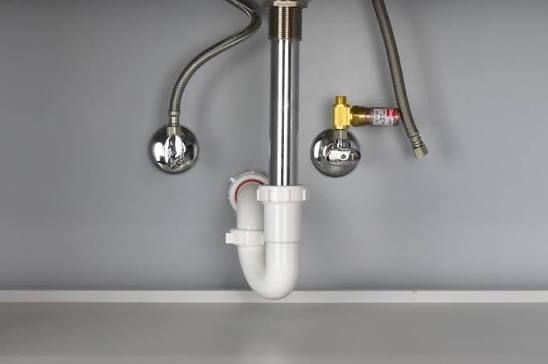
- Surge Suppression Devices: Install water hammer arrestors, surge tanks, or pressure relief valves (PRVs) near elbow bends and rapid shutoff points.
7. Are Digital Pressure Gauges Immune to Water Hammer, and How Do They Capture Peak Pressure?
Digital pressure gauges utilize solid-state semiconductor or piezoresistive sensors instead of mechanical Bourdon tubes, eliminating gear movements and pointers that can break mechanically. However, digital sensors still have maximum overpressure limits (Proof Pressure); if a water hammer spike exceeds this rating, the sensor element will sustain permanent damage.
- Range: 0...100 bar (1.5x Proof Pressure)
- Fast Response Time: < 50 ms
- 2.5" Backlit Display with Bargraph
- PEAK Hold feature captures fast surges
- Ultra-Wide Range: -1...2500 bar
- High Accuracy: ±0.05% FS
- 5-Digit Display with 5 Selectable Units
- Includes Filter, Tare, Zero & Peak/Valley
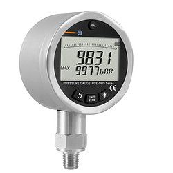
The PEAK Hold function on digital gauges allows engineers to capture millisecond-level transient pressure spikes, providing empirical data necessary to adjust valve closing times or size dampening accessories properly.
8. Frequently Asked Questions (FAQ) About Water Hammer & Pressure Gauges
This is a classic symptom of Bourdon tube permanent deformation caused by exposure to a water hammer pressure spike that exceeded the gauge's maximum pressure threshold.
A snubber does not alter the average static pressure reading. However, it dampens transient pressure spikes and slightly increases sensor response time.
Select Glycerine for standard temperature operating conditions (-20°C to +60°C). For extreme cold environments (-40°C) or wide temperature fluctuations, opt for Silicone oil filling.