Ultrasonic flaw detectors are used to check the quality of materials, helping to detect cracks, pores or impurities deep inside that are invisible to the naked eye. If you understand the correct operation of the machine and the working range of each type, users can choose the right equipment for the specific job, and at the same time better control the condition of the material during the production process.
Some fields today have researched the use of devices.
Ultrasonic flaw detectors are used in many different fields:
- Construction: checking welds, steel bars, concrete before use.
- Production and manufacturing: evaluating the quality of mechanical parts, metal materials before assembly or leaving the factory.
- Oil and gas and energy: detecting cracks, corrosion in pipes, pressure vessels or turbines.
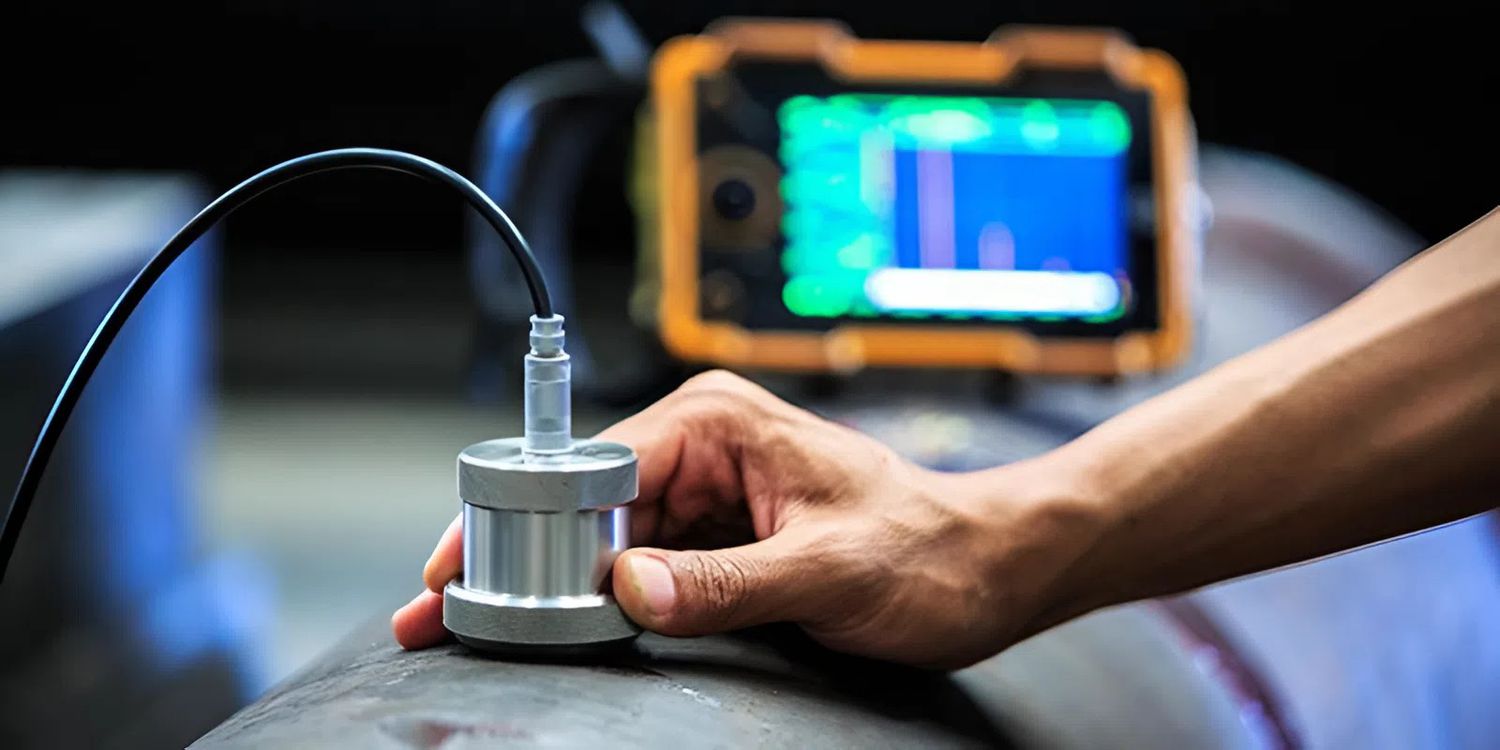
Thanks to its ability to detect errors quickly without causing damage to materials, ultrasonic methods have become a familiar inspection standard in today's industries.
Working principle of ultrasonic flaw detector
Ultrasonic flaw detectors operate based on the principle of sound wave feedback when encountering changes in the material structure.
When the probe emits an ultrasonic wave beam transmitted to the surface to be tested, the wave will bounce back if it encounters an abnormal boundary such as a crack, void or internal impurity. This feedback signal is recorded by the receiver and displayed on the screen in the form of wave pulses.
Operators rely on the time delay and echo amplitude to determine the location, depth and size of the defect.
This method is quite similar to the echolocation mechanism of bats or dolphins, when they broadcast and receive echo signals to recognize surrounding objects.
Structure of ultrasonic flaw detector
An ultrasonic flaw detector typically consists of four main components, designed to work together seamlessly throughout the inspection process:
- Ultrasonic probe (Transducer): emits and receives high-frequency sound waves, which are in direct contact with the test object.
- Signal amplifier: enhances weak feedback signals for the next analysis step.
- Central processor: receives feedback wave data and converts it into a graph or visual signal.
- Display screen: displays measurement results in real time, helping users easily observe and evaluate the material status.
Thanks to the combination of these components, the machine can detect defects inside the material quickly, clearly and is highly applicable in non-destructive testing.
Principle of transmitting and receiving ultrasonic waves
Ultrasonic flaw detectors operate based on the process of transmitting and receiving waves created by a probe containing a piezoelectric crystal. When an electric current passes through, the crystal vibrates and emits ultrasonic waves that penetrate deep into the material.
When the waves encounter areas with density changes such as cracks, voids or boundaries between two layers of material, part of the energy will be reflected back. The probe receives these reflected waves, converts them into electrical signals and sends them to the central processor to display the results on the screen.
Based on the transmission and reflection time of the wave, the device can determine the location and depth of the defect inside the object.
Feedback signal analysis
The feedback signal is displayed on the screen in the form of an A-scan graph consisting of many different wave peaks.
The first peak: represents the surface of the object being tested.
The next peaks: indicate the location of the defect or the bottom of the object.
The technician will observe the height, distance and shape of the wave peaks to identify the type of defect, and estimate their size and depth in the material.
Ultrasonic testing procedure
1. Preparation before testing:
Before measuring, the surface of the material needs to be cleaned to remove oil, dust or rust. A layer of couplant will be applied to the testing area to help the ultrasonic waves transmit better between the probe and the material. The operator chooses the appropriate probe type in terms of angle, frequency and diameter depending on the structure and characteristics of the sample. Parameters such as scanning range, amplification or sound transmission speed are also set according to the testing standards.
2. Test execution:
At the beginning, the probe is placed and moved evenly on the surface with the couplant. During the process, the display screen continuously reflects the signal from inside the material. If there are reflections that are different from the background area, it is an indication that a defect may exist. Suspicious locations will be noted for re-testing or further processing.
3. Analysis of results:
The collected data is compared with the evaluation criteria to determine the characteristics of the abnormal area. Based on the amplitude, shape and reflection time of the signal, the inspector can deduce the location, depth and type of defects such as cracks, porosity or delamination. All results are recorded in a report to serve the repair process, inspection or material quality assessment.
Popular ultrasonic flaw detectors currently distributed at EMIN
In the current market, ultrasonic detectors are often divided into two main groups: handheld and fixed lines, depending on the inspection needs and working environment.
Handheld ultrasound probe
Compact, flexible, convenient for field work or difficult-to-operate areas. Some popular models today include:
Huatec FD620: Durable structure, A-scan waveform display, good sensitivity, specialized in testing welds and metal parts.
HUATEC HPA-500: Supports saving and analyzing data directly on the machine, has automatic calibration function, suitable for engineers who often work outside the construction site.
Fixed ultrasonic detector
Suitable for production lines or inspection rooms where continuous testing and large number of samples are required.
Huatec HCDX-Y1: Automatic machine line, capable of direct connection to the central data management system, meeting the requirements of continuous testing in large-scale factories.