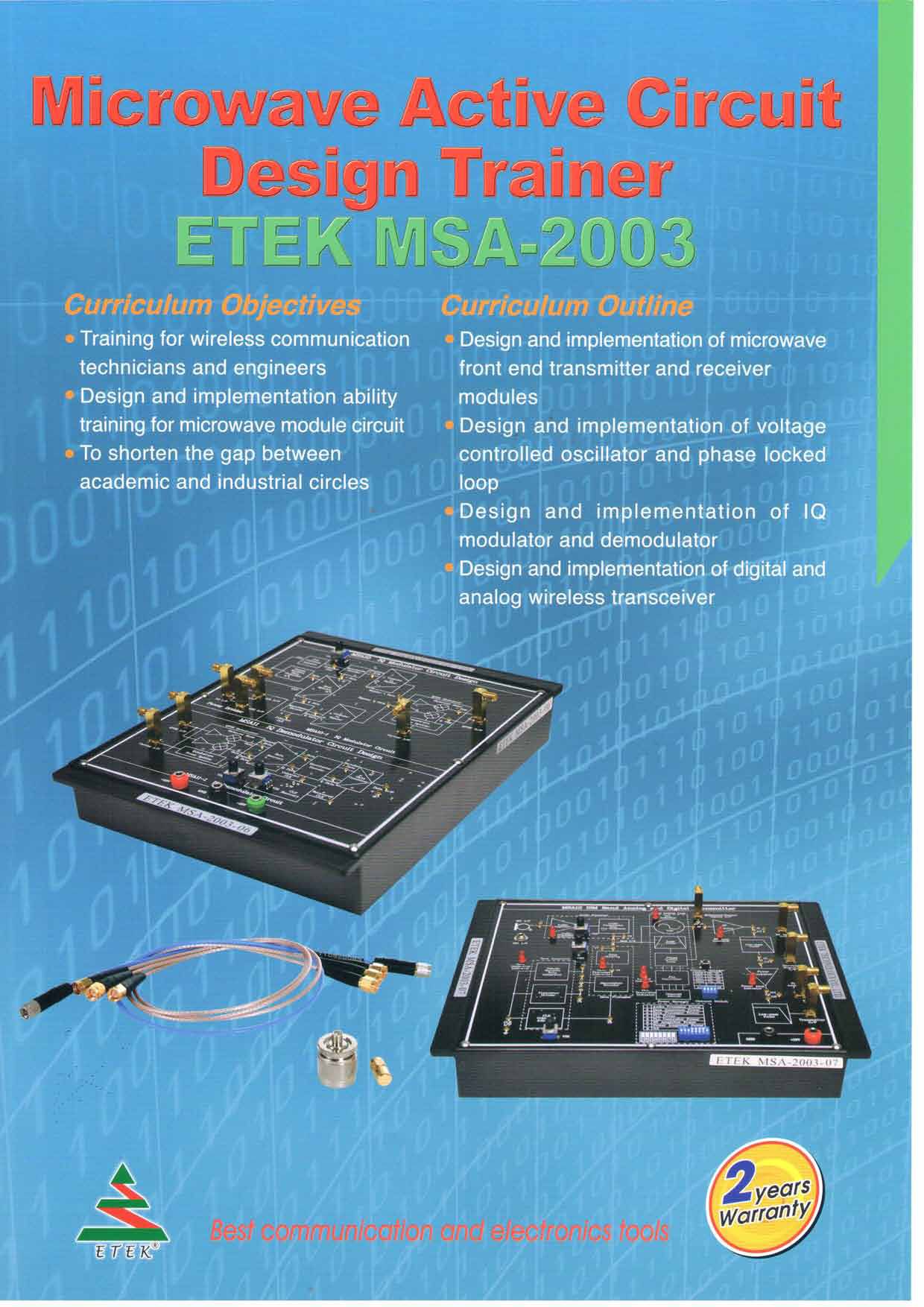
ETEK MSA-2003 微波有源电路培训套件 (8 Modules)
制造商: ETEK Model: MSA-2003 - 联系
Call for the best price
Hanoi city: (024) 35.381.269
Danang city: (023) 63.747.711
Bac Ninh city: (0222)730.39.68
HCM city: (028) 38.119.636
Module One: ETEK MSA-2003-01
Chapter 1: Design and Measurement of Microstrip Line Matching Circuit
Experiment 1: Measurement of Impedance Transformer Matching Network.
(Operation Frequency: 2400 MHz; S11 < -10dB )
Experiment 2: Measurement of Single and Balanced Short Stubs Matching Network
(Operation Frequency: 2400 MHz; S11 < -10dB )
Experiment 3: Measurement of Single, Balanced and Radio Open Stubs Matching Network.
(Operation Frequency: 2400 MHz;S11 < -10dB )
Experiment 4: Measurement of and Open Stubs Matching Network.
(Operation Frequency: 2400 MHz; S11 < -10dB )
Module Two: ETEK MSA-2003-02
Chapter 2: Design and Measurement of Low Noise Amplifier (LNA)
Experiment 1: Measurement of Frequency Responses
(Operation Frequency: 2350 ~ 2450 MHz; S11 < -10dB ,S22 < -10dB , S21 > 10dB )
Experiment 2: Measurement of Noise Figure
(Operation Frequency: 2350 ~ 2450 MHz; NF < 1.8 dB)
Experiment 3: Measurement of 1 dB Compression Point
(Operation Frequency: 2400 MHz; P1dB> -15 dBm )
Chapter 3: Design and Measurement of Voltage Controlled Oscillator
Experiment 1: Measurement of Oscillation Frequency and Output Power
(Oscillation Frequency: 2350~2450 MHz; Output Power: > -5 dBm)
Experiment 2: Measurement of Phase Noise
(Phase Noise: -90 ~ -100 dBc/Hz @ 100 kHz)
Experiment 3: Measurement of Gain Factor and Tunable Bandwidth
(Gain Factor: 10 ~20 MHz/Volt; Tunable Bandwidth: 60 ~ 70 MHz)
Experiment 4: Measurement of Pushing Figure (Pushing Figure: 8 MHz/Volt)
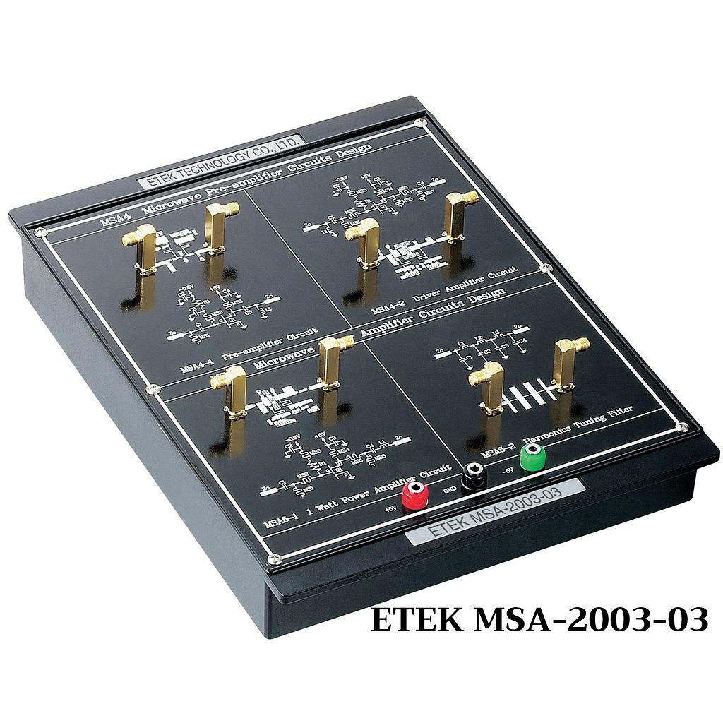
Module Three: ETEK MSA-2003-03
Chapter 4: Design and Measurement of Pre-Amplifier
Experiment 1: Measurement of Frequency Responses
(Operation Frequency: 2350 ~ 2450 MHz; S11< -10dB, S22< -10dB, S21> 10dB)
Experiment 2: Measurement of 1 dB Compression Point
(Operation Frequency: 2400 MHz; P1dB> 5dBm)
Experiment 3: Measurement of 3rd Order Intercept Point
(Operation Frequency: 2400 MHz; OIP> 25dBm)
Chapter 5: Design and Measurement of Power Amplifier
Experiment 1: Measurement of Gain Flatness
(Operation Frequency: 2350 ~ 2450 MHz; Gain Flatness:+- 1.5 dB)
Experiment 2: Measurement of 1 dB Compression Point
(Operation Frequency: 2400 MHz; P1dB > 23 dBm)
Experiment 3: Measurement of 3rd Order Output Intercept Point
(Operation Frequency: 2400 MHz; OIP3> 40 dBm)
Experiment 4: Measurement of the Ratio of Fundamental and Harmonics
(Operation Frequency: 2400 MHz:)
Module Four: ETEK MSA-2003-04
Chapter 6: Design and Measurement of Phase Locked Loop Controller
Experiment 1: LCD and Keypad Testing
(Locked Frequency Display: Locked Status Detection)
Experiment 2: MB 15E07 Control Signal Testing
(Locked Frequency: 2250 ~2350 MHz;
Stepped Frequency: 1 MHz, 10 MHz)
Chapter 7: Design and Measurement of Phase Locked Loop
Experiment 1: Measurement of Frequency Responses for Loop Filter
(3-dB Frequency: 12.5 kHz)
Experiment 2: Measurement of PLL and Phase Noise
(Phase Noise < -100 dBc/Hz @ 100 kHz)
Experiment 3: Measurement of PLL Locked Time (Locked Time < 5 ms)
Module Five: ETEK MSA-2003-05
Chapter 8: Design and Measurement of Balanced Mixer
Experiment 1: Measurement of Conversion Loss vs. LO Power
(RF: 2420 MHz, LO: 2350 MHz; Conversion Loss: < 15 dB)
Experiment 2: Measurement of Conversion Loss vs. RF Power
(RF: 2420 MHz, LO: 2350 MHz; Conversion Loss: < 15 dB, p1dB> 0dBm )
Experiment 3: Measurement of 3rd Order Intercept Point
(RF: 2420 MHz, LO: 2350 MHz; OIP> 10dBm )
Experiment 4: Measurement of IF bandwidth
(RF: 2360 ~ 2450 MHz, LO: 2350 MHz; IF bandwidth: > 100 MHz)
Experiment 5: Measurement of Isolation
(Operation Frequency: 2350 ~ 2450 MHz; Isolation: > 20 dB)
Chapter 9: Design and Measurement of Image-rejection Mixer
Experiment 1: Measurement of Conversion Loss vs. LO Power
(RF: 2420 MHz; LO: 2350 MHz; Conversion Loss: < 15 dB)
Experiment 2: Measurement of Conversion Loss vs. RF Power
(RF: 2420 MHz; LO: 2350 MHz; Conversion Loss: < 15 dB, P1dB> 5dBm )
Experiment 3: Measurement of 3rd Order Intercept Point
(RF: 2420 MHz; LO: 2350 MHz; OIP3> 15dBm )
Experiment 4: Measurement of Isolation
(Operation Frequency: 2350 ~ 2450 MHz; Isolation: > 30 dB)
Experiment 5: Measurement of Image-rejection level
(RF: 2250 ~ 2350 MHz; LO: 2350 MHz;
Image-rejection level: > 30 dB)
Module Six: ETEK MSA-2003-06
Chapter 10: Design and Measurement of IQ Modulator
Experiment 1: Measurement of PSK Modulator
(Operation Frequency: 70.7 MHz; Data Rate: >100 kbps)
Experiment 2: Measurement of QPSK Modulator
(Operation Frequency: 70.7 MHz; Data Rate: >100 kbps)
Chapter 11: Design and Measurement of IQ Demodulator
Experiment 1: Measurement of PSK Demodulator
(Operation Frequency: 70.7 MHz; Data Rate: >100 kbps)
Experiment 2: Measurement of QPSK Demodulator
(Operation Frequency: 70.7 MHz; Data Rate: >100 kbps)
Module Seven: ETEK MSA-2003-07
Chapter 12: Design and Implementation of Digital Wireless Transmitter
Experiment 1: Measurement of Output Power
(Operation Frequency: 2400 MHz; Pout> 10dBm)
Experiment 2: Measurement of Harmonics’ Output Power
(Operation Frequency: 2400 MHz; Pout< -45 dBm )
Experiment 3: Measurement of Modulation Signal
(Operation Frequency: 2400 MHz; Type of Modulation: FSK)
Module Eight: ETEK MSA-2003-08
Chapter 13: Design and Implementation of Digital Wireless Receiver
Experiment 1: Measurement of Sensitivity
(Operation Frequency: 2400 MHz; Receiver Sensitivity: > -80 dBm)
Experiment 2: Measurement of Demodulation Signal
(Operation Frequency: 2400 MHz; Type of Demodulator: FSK)
Experiment 3: Measurement of Image-rejection Ability
(Operation Frequency: 2400 MHz; Image-rejection level: > 30 dB)
Features
- 质量承诺
- 正品保修
- 送货到家
- 交易简单化