Frequency Counter & Analyzer Mini-Circuits
Solutions for measuring period and pulse width of electronic signals
Measuring period and pulse width serves as the foundation for evaluating frequency, stability, pulse width, duty cycle, and distortions occurring in electronic signals. To ensure accuracy, users need suitable equipment along with a proper measurement procedure, with particular attention to high frequency signals or pulse waveforms with small amplitude.
Basic concepts of pulse measurement
In electronic engineering, measuring period and pulse width are two key measurements for waveform analysis.
1. Pulse period (Period):
This is the time interval between two consecutive rising edges of a pulse train. From the period, the frequency can be derived using the formula f = 1/T
2. Pulse width (Pulse Width):
This is the duration during which the signal remains in the active state (HIGH or LOW). This value is typically measured at the fifty percent amplitude level to ensure consistency between measurements.
By mastering these two parameters, you can evaluate signal quality and detect faults in circuits, equipment, and control systems.
Instruments for measuring period and pulse width
To perform period and pulse width measurement with high accuracy, the two most commonly used groups of instruments are digital oscilloscopes and frequency counters.
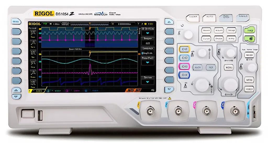
A digital oscilloscope is the optimal instrument for analyzing and measuring electronic signals thanks to its ability to display waveforms visually and provide automatic measurement features. It can automatically measure parameters such as Period, Pulse Width, Frequency, and Duty Cycle, with direct waveform display to help verify errors, noise, and jitter.
For complex and varying pulse waveforms, the oscilloscope is always the preferred choice due to its many features such as support for advanced trigger modes for difficult to measure pulses, easy data storage and export, and highly accurate repeatable measurements.
When extremely fine time resolution is required or when measuring very high frequency signals, a dedicated frequency counter or pulse counter is the appropriate solution.
Some models such as the TTI TF930 frequency counter, the KEYSIGHT 53230A frequency counter, and the PICOTEST U6220A frequency counter integrate features such as the use of an internal reference timebase for time measurement, along with the ability to measure period and pulse width with absolute stability. These measurements are less dependent on waveform display, help avoid operator reading errors, and make pulse counters particularly useful in laboratories, production lines, or automated measurement environments.
Correct measurement procedure
No matter how advanced the equipment is, a correct measurement procedure is always the decisive factor. When measuring period and pulse width, users can refer to the following procedure:
Step 1: Connect and set up the display, adjust the voltage and time scales so that one to two stable cycles of the pulse waveform are displayed.
Step 2: Select a stable trigger to keep the waveform fixed, whether performing automatic or manual measurement.
Step 3: Perform automatic measurement or measurement using cursors. Automatic measurement via the Measure function provides quick results, while manual cursor measurement is suitable for older instruments.
For example, the OWON XDS3102 digital oscilloscope includes many integrated automatic measurements such as Period, Frequency, Pulse Width.
Step 4: Ensure the measurement point is at the fifty percent amplitude level to define stable pulse edges and reduce error when pulses have shallow slopes or noise.
Step 5: Apply averaging in noisy environments when using modern instruments that support averaging.
In addition to selecting standard and reputable equipment, periodic calibration of oscilloscopes, probes, and counters is mandatory to obtain the most reliable period and pulse width measurement results. Instruments with a stable reference timebase, high quality probes, and proper settings will minimize measurement errors, especially when working with complex, noisy, or high frequency signals.
-
-
-
-
-
-
-
-
-
-
-
-
-
-
-
-
-
-
-
-
-
-
-
-