This method is both cost-effective and easy to implement while still ensuring high enough accuracy to evaluate inductance values in laboratory or production line environments.
First of all, what is inductance?
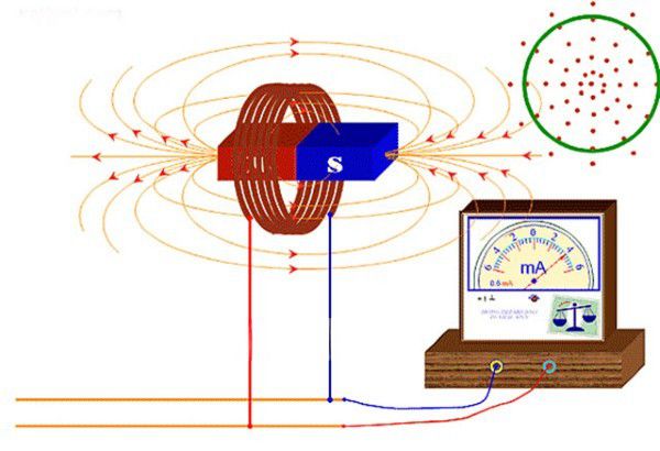
Inductance is a quantity that characterizes the ability of an electric circuit to create a magnetic field when an electric current flows through it. When the current changes, the magnetic field generated around the conductor also changes, thereby forming an induced electromotive force that tends to oppose the initial change in the current.
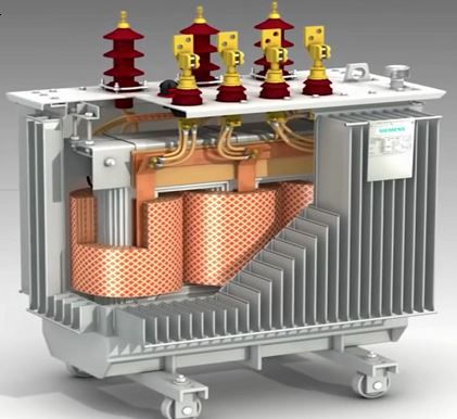
The value of inductance depends on three main factors: the current intensity, the number of turns of the inductor and the physical properties of the conducting material. This quantity is measured in henry units, expressed as the ratio between the induced voltage across the inductor and the rate of change of the current flowing through it.
Inductance and the principle of formation of induced electromotive force
To measure inductance, a simple resonant circuit consisting of an inductor, capacitor, and resistor can be set up. A sinusoidal voltage waveform generated by a signal generator is fed into the circuit, while an oscilloscope is used to observe the voltage across the inductor to determine the resonance point.
The principle of this method is based on the resonance characteristics between the inductor and the capacitor. When the circuit reaches the resonant frequency, the total impedance of the circuit reaches a minimum and the voltage reaches a characteristic value. Knowing the value of the capacitor and the resonant frequency, the inductance can be calculated according to the formula:
L = 1/(4π²f²C)
Where:
L is inductance (in henry units)
f is resonant frequency (in hertz units)
C is capacitance (in farad units)
Criteria for selecting inductance measuring device
When selecting the right instrument for measuring inductance, it is important to consider core technical factors such as operating frequency range, accuracy, resolution and user-friendliness. First, you need to clearly define the frequency range in which the circuit will operate so that you can choose a device that can fully cover that frequency range. For high-precision measurement requirements, specialized instruments such as LCR meters or network analyzers will be the preferred choice, outperforming general-purpose oscilloscopes or cable testers.
In addition to technical factors, ease of use should also be considered, especially if this is the first time performing measurements. An intuitive interface and simple operation will reduce errors and increase processing efficiency. Finally, the choice of equipment should harmonize between budget and actual measurement requirements, to ensure long-term investment efficiency.
Why should we use oscilloscope and signal generator to measure inductance?
Although there are many different methods of measuring inductance, Rohde-Schwarz SIGNAL GENERATOR and an oscilloscope is still the preferred choice for basic applications. The first reason is the cost. Compared to an LCR or a network analyzer, this pair is more reasonable in price, suitable for most technicians, students or small labs.
In addition, these two devices are easily accessible, popular in most electronics labs and can be deployed quickly thanks to a friendly interface. For circuits operating in the mid-frequency range and requiring less stringent accuracy, this method still ensures the necessary reliability.
However, it should be noted that this method of measurement will be limited in accuracy, frequency range and requires manual calibration. Therefore, if the system operates at high speeds or requires complex differential measurements, more specialized equipment should be considered.
Troubleshooting Tips for Measuring Inductance
Oscilloscope and signal generator inductance measurements can sometimes be subject to errors due to noise, unstable connections, or improper adjustment. The following tips will help you handle these situations effectively.
Adjust signal frequency and amplitude
Set the frequency within the range appropriate to the characteristics of the inductor and the limits of the measuring instrument. If the signal is distorted or unclear, recalibration may be necessary. If the amplitude exceeds the threshold, use a voltage divider or attenuator to reduce the signal level applied to the circuit.
Ensure signal amplitude is within operating range
Signal amplitudes that are too low will be difficult to observe, while those that are too high may cause distortion or damage to the device. Check the voltage rating of the inductor and ensure that the input signal does not exceed the allowable level.
Check connection
Các tiếp điểm lỏng lẻo sẽ khiến kết quả đo sai lệch và có nguy cơ gây hỏng cổng thiết bị. Trước khi thực hiện phép đo, cần rà soát lại toàn bộ kết nối, cáp tín hiệu và điểm tiếp xúc.
Check ground connection
One of the most common causes of inaccurate measurements is improper grounding. Use a device such as a multimeter or induction tester to verify ground continuity. Make sure all devices, inductors, and signal sources are securely grounded.
If you find a ground loop causing interference, use a ground isolator to eliminate it and improve measurement accuracy.
Check for noise
Electromagnetic and high frequency noise are major factors affecting inductance measurements. Check the input signal and eliminate noise sources if present. Locate the system away from noise sources such as power lines, transmitters or fluorescent lights. The signal cable should be shielded. If necessary, combine with a low-pass filter or noise shield.
Use another inductor
If the signal is still unstable after checking, the cause may be in the inductor being used. Replace it with another inductor with suitable specifications. Pay attention to the nominal inductance, current limit, voltage and working environment conditions to choose the correct replacement part.
Verify oscilloscope settings before measuring inductance
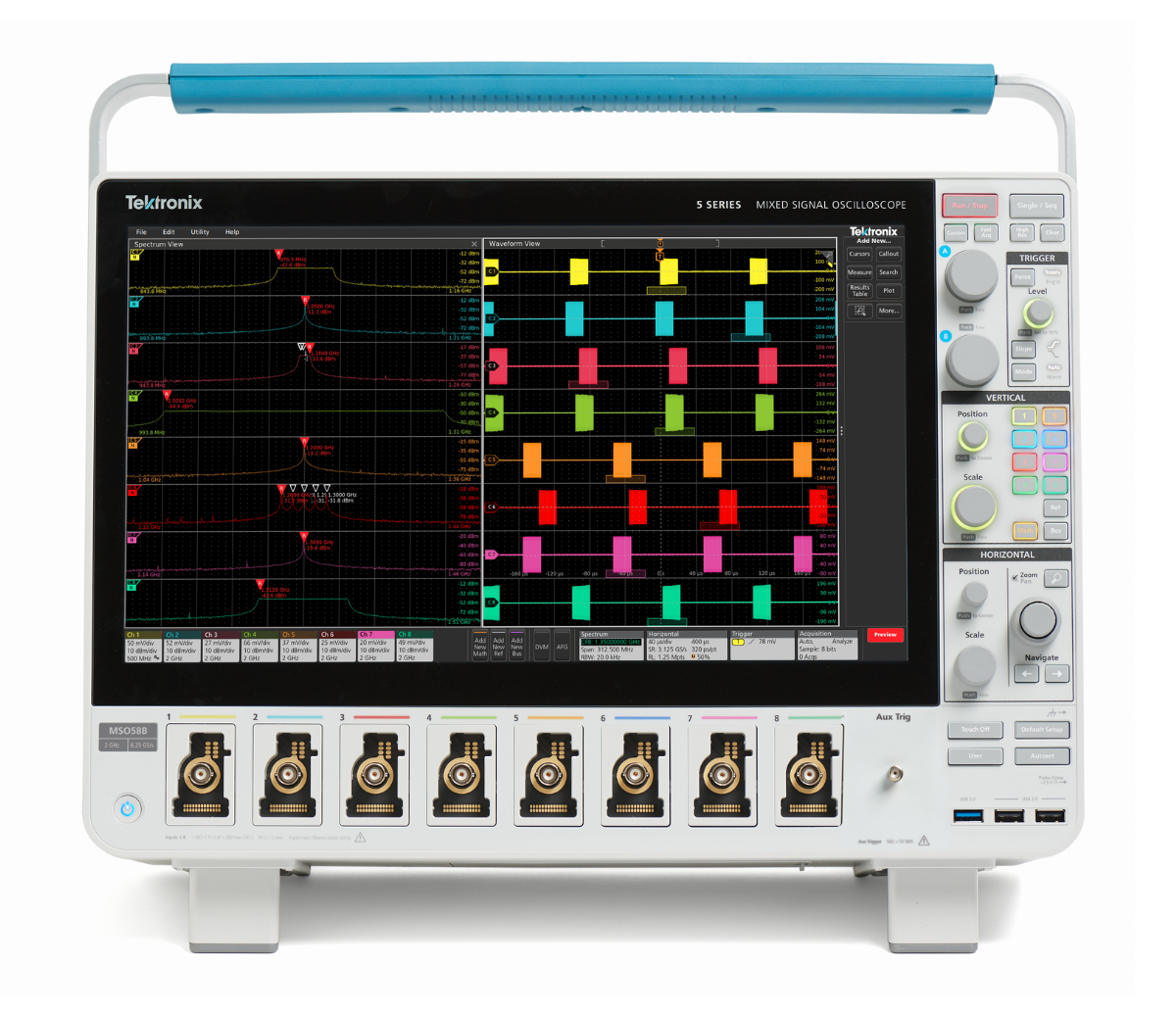
Before measuring inductance with an oscilloscope, it is necessary to fully set the range parameters to ensure accurate measurements. Make sure you have selected the correct vertical and horizontal scales and set the appropriate trigger level. In some cases, it is necessary to calibrate the gain to make the signal display clear and stable.
The voltage scale should be adjusted so that the voltage across the inductor occupies about one-third of the full range displayed on the vertical axis. Regarding the time, choose a time scale that allows you to observe many signal cycles, making waveform analysis easier and more intuitive.
In addition, determining the correct measurement window size is also important. If the display window is too narrow or inappropriate, the signal may be distorted or lost, causing errors in the data recording process. Before starting the measurement, it is necessary to ensure that the oscilloscope is properly calibrated and is operating stably within the required parameter range.
The method of measuring inductance using an oscilloscope combined with a signal generator offers a great advantage in terms of real-time signal monitoring. Especially in applications that require continuous monitoring or evaluating components under changing conditions, this is a reliable and cost-effective option.