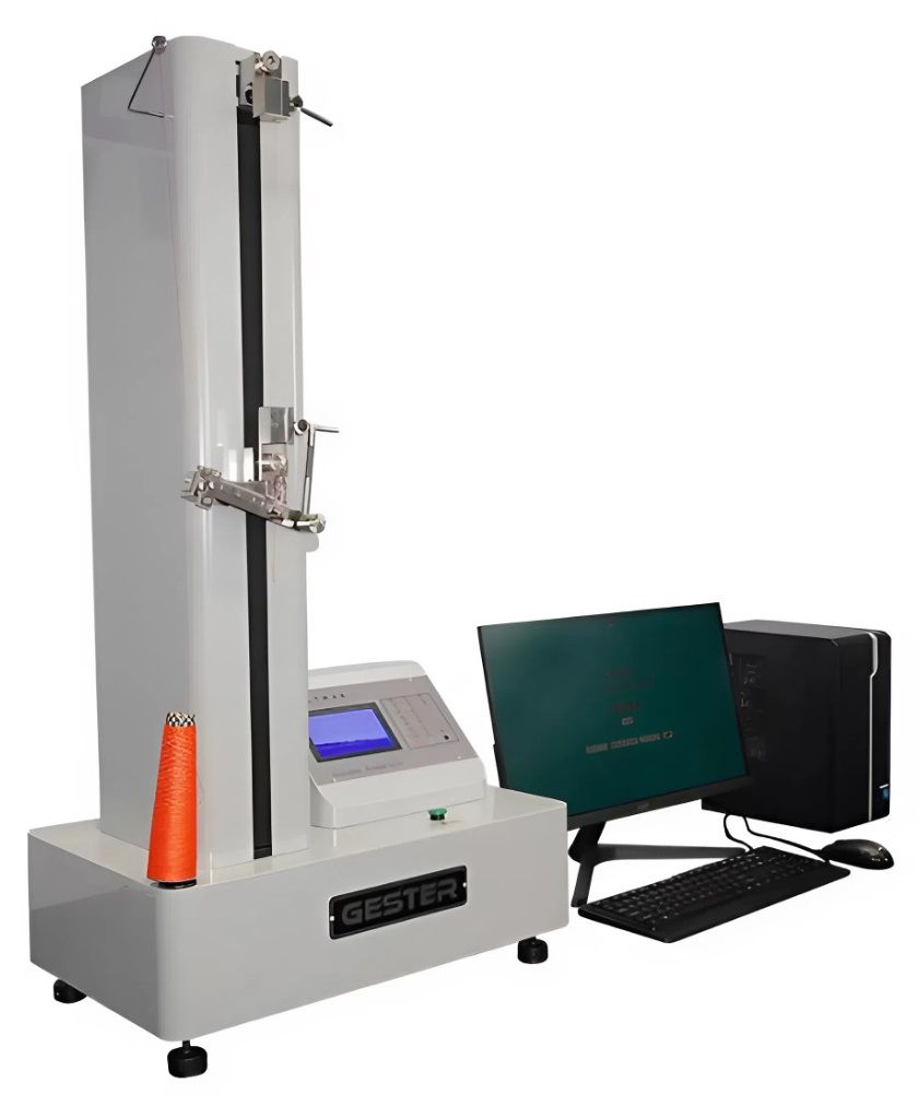
The GT-A01 Single Yarn Strength Tester is intended for evaluating two important single-yarn properties: breaking strength and elongation. For textile laboratories and manufacturing quality teams, these measurements can provide a structured basis for reviewing yarn performance, comparing test results, and supporting routine quality-control decisions.
Purpose of the GT-A01 Single Yarn Strength Tester
Yarn strength and extension are important performance indicators in textile testing. The GT-A01 Single Yarn Strength Tester is designed to determine the breaking load and extension of individual yarn specimens. It is therefore relevant where a team needs to test various yarns and record the results in a consistent workflow.
Single Yarn Strength Tester measures breaking load and extension within a range of 5000 centi-grams force. Its force scales are listed as 0–500 cg force and 0–5000 cg force. Extension can be read in millimetres and as a percentage of the stated 500 mm standard test length.
This scope makes the tester suitable for textile testing laboratories and quality-control departments in manufacturing environments. Rather than relying only on visual checks, users can review recorded force and extension data from repeated tests on comparable samples.
Key functions for yarn testing workflows
The GT-A01 combines electronic operation with mechanical action. Its dynamic data sampling frequency is stated as over 800 Hz, a feature intended to help capture peak values during a test. This can be useful when reviewing the breaking event and the associated extension result.
Data visibility during testing
A blue LCD panel provides the operating interface. The interface is described as presenting commands relevant to the selected task, while graphical button icons indicate their functions. During a test, the system can display ongoing information such as mean square value, average, maximum, and minimum values in real time.
The product information also identifies a Mitsubishi 16-bit MCU and an A/D converter. These components are described as supporting anti-interference performance and rapid data transfer. When assessing an instrument for routine use, teams may consider how this interface and data display approach fit their existing laboratory procedures.
Results handling and comparison
Test reports and diagrams can be processed on a computer and printed. Data can also be exported to Excel for further analysis, and curves can be overlaid for comparison. These functions can assist users who need to compare individual test runs, review statistical values, or retain historical records.
The unit is also described as supporting bidirectional control. Operators can use the LCD control panel to operate the tester and print test data without a PC. The source information notes, however, that control-panel testing is intended for demonstration and is not recommended when data must be printed on a specified printer.
Basic installation considerations
Before operation, the tester should be level. The documented procedure calls for checking the four corners with a spirit level and adjusting uneven corners with a spanner. A stable, level position helps establish a consistent setup before specimens are tested.
The supplied installation guidance specifies connecting the data cable, confirming an AC220V power supply, connecting the power cable, and switching on the unit. The computer can then be turned on and the testing software opened. Users should follow the applicable operating instructions for their own equipment configuration.
Typical test sequence
- Start a new test and enter the relevant test information and parameters.
- Proceed to the test interface. The lower fixture is described as automatically searching for the gauge distance.
- Install the specimen and select the appropriate tension weight according to yarn density.
- Start the test using the software command or the green START button.
- Review the displayed result after completion and repeat the method for additional specimens as needed.
- Check results in the Single test data area, then use Statistical value to process the collected data.
- Save the data, print a report file when required, and use Browsing to review historical data.
Supporting textile quality control
Consistent specimen handling, repeated testing, and organized result review are central to a practical yarn-testing process. The GT-A01 Single Yarn Strength Tester brings these steps together through force and extension measurement, real-time values, statistical processing, data saving, and report handling.
For organizations working with single yarn evaluation, Single-yarn tensile strength tester can support a more traceable approach to reviewing breaking strength and elongation data. Final test methods, sample preparation, parameter selection, and acceptance criteria should be defined by the laboratory or manufacturer’s own quality procedure.