For full functionality of this site it is necessary to enable JavaScript.
EMIN.ASIA
0

Test on 13MHz RFID Tag-RLB Test Method

02/10/2018 10:17:05

Test on 13MHz RFID Tag-RLB Test Method Radio Frequency Identification (RFID), a wireless RF identification system, utilizes radio frequency (electromagnetic sensing, microware, etc.) to conduct the transmission, identification and swapping of wireless information.

Radio Frequency Identification (RFID), a wireless RF identification system, utilizes radio frequency (electromagnetic sensing,microware, etc.) to conduct the transmission, identification and swapping of wireless information. A complete RFID includes electronic tag (Tag), reading device (Reader) and main computer (Host). This application uses RLB to test the common 13MHz RFID Tag. This test method can also be applied for production line to rapidly compare the result with Golden Sample.


The Basic Understanding of the Test

The test method of RFID Tag utilizes RLB and RFID Tag fixture. After connecting TG, fixture and RF terminal, normalize the signal and place DUT at the center of fixture to obtain Tag's frequency range.

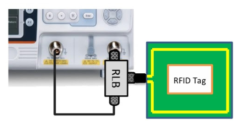
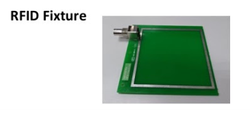
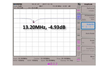
Illustration of Curve

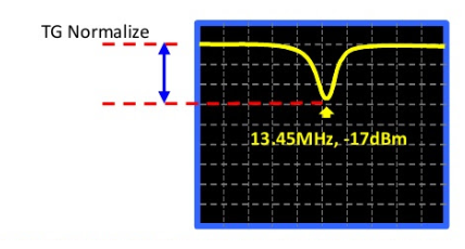
This test method aims at obtaining the Return Loss data of DUT to find out its main operating frequency. The amplitude difference under TG Normalize line is the real test difference.

Required Equipment

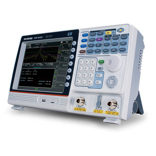
GSP-9330 / GSP-9300B

Option 01: Tracking Generator

RLB-001: 1GHz Return Loss Bridge GKT-003: RLB Kit

GW RFID Tag Fixture

ADP-001 : N(M)-BNC(F) Adapter

Test Procedures

1.Connect TG, RF, RLB-001 and RFID Fixture

2.Activate GSP-9330 TG function

3. Execute TG Normalize

4.Connect DUT (RFID Tag)

5.Use Min.Peak Search to obtain the frequency of the lowest amplitude

Test Result

Related News

Downtime Doesn't Strike Suddenly: Many Factories Lose Hundreds of Hours of Production by Overlooking Subtle Warning Signs
06/25/2026 14:15:17

For many factories, downtime is often viewed as an unexpected event that strikes during a production shift. In reality, however, the situation is different. Before a motor fails, a variable frequency drive (VFD) reports an error, or a production line requires an emergency stop, the equipment typically emits multiple warning signals—such as abnormal temperature rises, excessive vibration, degraded power quality, or unstable communication performance. These indicators can persist for days or even months before an actual breakdown occurs

Micsig MOIP Series: Comprehensive testing solution for high-power three-phase inverters
06/22/2026 11:36:21

The widespread adoption of wideband semiconductor components such as SiC and GaN in photovoltaic inverters, motor drives, and automotive charging systems has driven the switching frequency and power density of three-phase inverters to unprecedented levels. However, this development has also brought with it severe measurement challenges: high voltages, intense electromagnetic interference, and the requirement for ultra-fast switching signal capture at the nanosecond scale

Stay Updated with Offers

Get exclusive volume discounts, bulk pricing updates, and new product alerts delivered directly to your inbox.

By subscribing, you agree to our Terms of Service and Privacy Policy.

Quick Support

Direct access to our certified experts