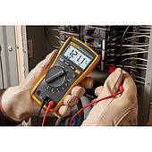
When two multimeters show different readings, instead of immediately deciding which one is incorrect, it is better to evaluate the waveform, the type of load in operation, and the measurement capability of each instrument.
Measuring the Same Voltage Does Not Always Mean Reading the Same Signal Characteristic
AC voltage does not exist as a fixed value; it continuously changes over time. A multimeter must capture the signal, process it, and convert it into a representative value that users can interpret easily.
With stable power sources and near-sinusoidal waveforms, measurement results between different instruments are usually quite consistent.
However, once electronic loads such as variable frequency drives (VFDs), switching power supplies, speed controllers, UPS systems, or high-power LED lighting are introduced, the waveform begins to change.
At that point, even at the same measurement location, instruments based on different measurement principles may produce results that are not exactly identical.
Where Do RMS and True RMS Start to Diverge ?
If the signal remains close to a pure sine wave, conventional RMS and True RMS readings generally show very little difference.
That is why users performing residential electrical measurements or basic power checks often do not notice any distinction between meter types.
The difference becomes more noticeable when the signal contains pulse modulation, peak distortion, or periodic waveform variations.
Some multimeters true RMS values from average measurements. This method is fast and suitable for many routine inspection tasks.
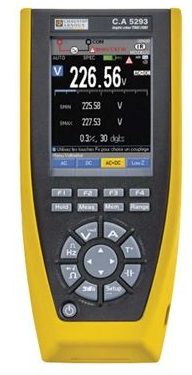
True RMS meters, by contrast, process the entire waveform to calculate the actual effective value of the signal at the time of measurement.
When measuring inverter outputs or electronically conditioned power sources, the two instruments may begin displaying different values even while connected to the same circuit.
Measurement Differences Are Not Always Caused by the Multimeter
If changing the meter still produces varying results, measurement conditions should also be considered.
Signals measured at load outputs, electrical panels, or switching points do not always remain constant over time. Sampling moments separated by only a few seconds can sometimes create visible differences on the display.
In addition, manufacturers implement different signal-processing strategies. Some devices prioritize fast response to follow fluctuations closely, while others smooth the signal to provide more stable readings.
Choose a Multimeter Based on the Type of Signal You Measure
True RMS capability is often considered an upgrade feature, but its value depends heavily on the operating environment.
When working with variable frequency drives, automation systems, power electronics, or monitoring actual load behavior, the ability to correctly interpret distorted waveforms becomes more beneficial.
If the main task is residential electrical inspection or verifying basic supply voltage, a standard RMS meter is usually sufficient.
When selecting a multimeter, a useful starting point is asking: “What type of signal am I measuring?” Measurement results are always influenced by both the signal-processing method of the instrument and the conditions at the time of testing.
Frequently Asked Questions (FAQs)
Does a True RMS multimeter always provide more accurate results ?
Not in every situation. With stable AC signals, the difference between meter types is often minimal. The advantage of True RMS becomes clearer when measuring electronic loads or distorted waveforms.
Is True RMS necessary for normal residential electrical measurements ?
If the goal is simply checking outlet voltage or confirming power availability, a standard multimeter is usually sufficient. More advanced measurement needs depend on the type of load being evaluated.
Why does the reading change over time at the same measurement point ?
Changes in electrical load, source fluctuations, or differences in how the instrument processes signals can all affect measurement results between readings.
Can a True RMS multimeter replace a power quality analyzer ?
No. A multimeter is useful for quickly evaluating electrical values but does not replace dedicated instruments designed for waveform analysis, electrical noise evaluation, or power quality assessment.
Can waveform distortion be identified directly from the meter display ?
Usually not. More common indicators include unstable readings or noticeable differences between multiple measuring instruments under the same conditions.
Related Articles