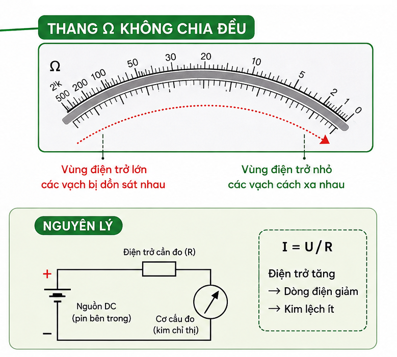
When looking at the dial of an analog multimeter, the Ω resistance scale is noticeably different from the voltage or current scales. The graduations near 0 Ω are spaced farther apart, while the spacing becomes progressively narrower toward ∞ Ω.
This results from the non-linear principle used to measure resistance in an analog VOM. The instrument does not measure the Ω value directly. Instead, it uses an internal battery to drive current through the resistance being tested. The meter movement then converts changes in current into needle deflection.
Resistance and Current Determine the Shape of the Ω Scale
The resistance measurement principle of an analog multimeter is based on the relationship between voltage, current, and resistance:
I = U/R
In the measurement circuit, the battery supplies voltage that drives current through the resistance under test. When the resistance is low, the current is high and the needle deflects more. As the resistance increases, the current decreases and the needle moves less.
Current Does Not Change Linearly with Resistance
For example, when resistance increases from 10 Ω to 20 Ω, the current changes significantly. But when resistance increases from 1,000 Ω to 1,010 Ω, the change in current is much smaller.
The meter movement responds to current. Therefore, the same amount of needle movement cannot represent the same change in resistance.
That is why the Ω scale on an analog multimeter must be graduated non-linearly. Lower resistance values are spread farther apart across the scale, while higher values become increasingly compressed toward ∞ Ω.
Why Is 0 Ω on the Right and ∞ Ω on the Left?
The Ω scale on an analog multimeter is normally read in the opposite direction from the V or A scales.
When the two test leads are left open, almost no current flows through the meter movement. The needle rests at the position corresponding to ∞ Ω.
When the two test leads are shorted together, the external resistance is approximately 0 Ω. The current in the measurement circuit rises to its maximum designed level, causing the needle to deflect fully toward 0 Ω.
The scale therefore appears as:
∞ Ω ← intermediate values → 0 Ω
This is also why the two test leads should be shorted and the Ω Zero adjustment set to 0 Ω before measuring resistance.
If the needle cannot reach 0 Ω even when the test leads are shorted, check the battery, test leads, contact points, and measurement circuit.
The Uneven Ω Scale Allows a Wide Resistance Range to Be Read
A uniformly divided scale would not match the characteristics of resistance measurement. If the Ω values were arranged linearly, high resistance values would be compressed into a very small section of the dial, making them difficult to read.
A non-linear scale makes better use of the needle's full range of movement. This is an important design feature of an analog multimeter: the scale is designed according to the characteristics of the meter movement rather than divided into mechanically equal intervals.
Ranges such as ×1, ×10, ×100, and ×1k further extend the measurable resistance range.
For example, if the needle points to 30 on the Ω scale and the range selector is set to ×100:
R = 30 × 100 = 3,000 Ω = 3 kΩ
If the needle is too close to either ∞ Ω or 0 Ω, switching to another range can place the needle in an area with wider, easier-to-read graduations. The selected range directly affects how accurately the value between scale markings can be estimated.
With an analog VOM, the uneven Ω scale is simply how the dial represents a measurement with a non-linear characteristic.
The Battery and Test Leads Can Affect the Ω Reading
The Ω range uses the internal battery to generate the test current. When the battery becomes weak, the voltage supplied to the measurement circuit decreases, and the needle position may no longer correspond accurately to the Ω scale.
This is why the Ω Zero adjustment should be performed before each resistance measurement. If the needle still cannot be set to 0 Ω after shorting the test leads, the battery should be checked.
For low-resistance measurements, the test leads and contact points also affect the result. If an analog multimeter still shows a small resistance value instead of 0 Ω when the test leads are shorted, the difference may come from the resistance of the leads, probe tips, and contact points.
This is particularly relevant when using an electrical multimeter to check wires, fuses, coils, or very low-value resistors.
How to Read the Resistance Scale on an Analog Multimeter
The Ω scale should not be read in the same way as the V or A scales. The user needs to identify the correct Ω scale, check the 0 Ω position, select the appropriate multiplier, and then read the value.
Conversely, selecting a range that is too low for a high-resistance component may cause the needle to move close to 0 Ω, making the reading difficult.
A suitable range is one that places the needle in an area where the graduations are sufficiently wide for easy observation and interpolation.
A digital multimeter also measures resistance based on the same electrical relationships, but the signal is processed electronically before the result is displayed as a numerical value.
Understanding this principle helps users read the Ω scale correctly, select an appropriate measurement range, and identify factors that can affect accuracy, such as a weak battery, test-lead resistance, or poor electrical contact.