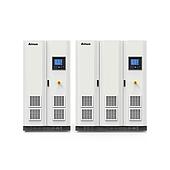
A traditional DC test power supply is suitable when a device only needs stable, controlled voltage or current. A battery simulator is more appropriate when the test must represent the changing terminal behavior of a lithium battery.
Based on the provided ANEVS series information, the distinction centers on dynamic battery modeling, energy handling, switching behavior, and the ability to run more complex charge and discharge scenarios.
Summary: DC power supplies provide stable DC output for basic tests. ANEVS battery simulators are designed to model changing battery behavior. The supplied information also describes regenerative energy handling and programmable test scenarios.

What is the main difference between a battery simulator and a DC power supply?
The central difference is the intended output behavior. A conventional DC test power supply is intended to maintain a set voltage or current, whereas a battery simulator is intended to reproduce how battery terminal voltage changes as operating conditions change.
Lithium battery behavior is described in the source as nonlinear and dependent on state of charge (SOC), temperature, state of health (SOH), and charge or discharge current. This makes a fixed-output source less representative when the device under test needs to interact with a changing battery model.
Why can a fixed DC power supply be limited for lithium battery simulation?
A fixed DC source may not reproduce dynamic internal resistance or the nonlinear relationship between open-circuit voltage (OCV) and SOC. In an actual battery, a current change can alter terminal voltage through internal resistance, creating a voltage dip or rise.
The supplied information also notes that a simple voltage setting or sequence may not represent plateau regions or steeper voltage changes near battery depletion. These characteristics can matter when evaluating functions such as BMS voltage measurement, protection timing, or fuel-gauge algorithms.
| Test consideration | Traditional DC test power supply | Battery simulator (ANEVS) |
|---|---|---|
| Primary purpose | Provides stable DC power | Simulates battery behavior |
| Internal resistance behavior | Typically fixed output impedance | Described as dynamically adjustable |
| SOC-OCV relationship | Difficult to represent with a fixed setting | Described as customizable |
| Energy during testing | May be dissipated as heat in conventional load operation | ANEVS is described as feeding energy back to the grid |
| Complex operating conditions | More difficult to implement | Supports programmable simulation functions |
How does a battery simulator represent SOC, OCV, and internal resistance?
The ANEVS series is described as using battery mathematical models whose parameters can include battery type, capacity, internal resistance, and an SOC-OCV curve. The goal is to calculate terminal-voltage behavior in real time as the modeled battery condition changes.
This approach can be relevant when a test needs more than a fixed supply value. For example, the source identifies charge and discharge behavior, voltage recovery after load removal, and aging-related increases in resistance or capacity loss as scenarios that are difficult to recreate with basic equipment.
How is energy handled during battery discharge simulation?
When equipment under test sends energy back during a discharge-related simulation, conventional electronic loads commonly convert that energy into heat. The supplied ANEVS information states that the series recycles discharged energy and feeds it back to the grid.
The source claims energy recycling above 90% and energy savings above 80%; these figures should be read as series-level claims from the supplied material, not as a guaranteed result for every setup. Heat generation and actual savings can depend on the test configuration and operating conditions.
Note: Energy-saving and regeneration results should be evaluated against the specific test profile, connected equipment, and installation conditions.
Why do switching speed and overshoot matter in battery tests?
Battery-related tests can require transitions between constant-current (CC) and constant-voltage (CV) operation. The source states that conventional supply or load switching can have millisecond-level delay, which may lead to voltage or current overshoot.
For ANEVS, the supplied information describes digital control with nanosecond-level switching and an overshoot-free design. Such behavior is presented as useful for protecting sensitive devices under test and for evaluating equipment that uses smart charging protocols.
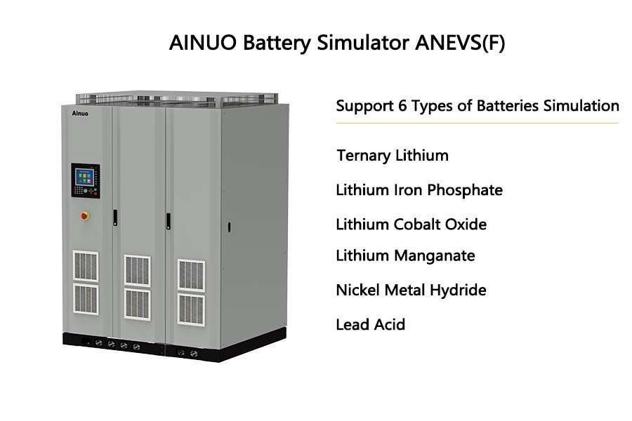
What test scenarios can the ANEVS series support?
The provided information describes programmable charge and discharge curves, pulse conditions, battery aging simulation, and multi-step test sequences. It also lists battery simulation, standard power, standard load, and CR-LED modes.
These capabilities may be relevant to BMS development, portable electronics, new-energy vehicle motor controllers, and energy-storage PCS testing when the purpose is to assess operation under modeled battery conditions rather than only verify basic DC input behavior.
When should you choose a DC power supply instead of a battery simulator?
Choose a traditional DC test power supply when the requirement is straightforward voltage or current delivery and battery-specific behavior is not necessary. It can be a practical fit for basic supply tests where a stable setpoint is the key condition.
Choose a battery simulator when the test requires modeled SOC-OCV behavior, variable internal resistance, programmed cycles, pulse conditions, or battery aging effects. The appropriate choice depends on whether the device must be validated against a stable DC source or a changing battery-like electrical response.