DC fast charger testing can use a high-power bidirectional DC electronic load to reproduce battery-side conditions without connecting an actual vehicle battery. This approach is intended for evaluating DC charger output under controlled voltage, current, power, resistance, and battery-simulation settings.
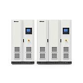
The Ainuo ANEL(F) series is presented as a source-load integrated electronic load for this application. Its listed functions include battery simulation, programmable operation, parallel configurations, and power feedback.
Summary: DC fast charging requires higher-power test equipment than many AC charging applications. A bidirectional DC load can simulate battery behavior and operate in CV, CC, CP, and CR modes. The ANEL(F) specification list includes response time of ≤3 ms, power feedback above 90%, and support for seven battery types.
What is a bidirectional DC electronic load used for in DC fast charger testing?
A bidirectional DC electronic load is used to emulate the electrical behavior of an EV battery while a DC charger is under test. It provides a controlled load condition and, where power feedback is available, can return absorbed energy rather than dissipating all of it.
This is relevant because DC chargers operate at higher power than AC charging equipment. The source material notes that a single DC charging module can reach 30 kW and that some tested super-charging systems have reached 1 MW.
Why is battery simulation important when testing a DC fast charger?
Battery simulation allows a laboratory to set repeatable test conditions without relying on a physical battery pack. For the ANEL(F) series, the listed adjustable battery-related parameters include cell capacity, series-parallel arrangement, state of charge (SOC), and temperature.
The specification list also states support for first-, second-, and third-order battery models and internal-resistance models. CSV and MAT data import and export are listed, which can support the use of defined battery-model data in a test workflow.
Which battery chemistries can the ANEL(F) series simulate?
The ANEL(F) series specification list identifies seven battery types: ternary lithium, lithium iron phosphate, lithium titanate, lithium cobalt, lithium manganate, nickel-metal hydride, and lead-acid. The available simulation type should be matched to the battery behavior required by the charger test plan.
| Listed battery simulation types | Examples named in the specification |
|---|---|
| Lithium battery types | Ternary lithium, lithium iron phosphate, lithium titanate, lithium cobalt, lithium manganate |
| Other battery types | Nickel-metal hydride, lead-acid |
Which operating modes are available for charger load testing?
The listed operating modes are CV, CC, CP, and CR: constant voltage, constant current, constant power, and constant resistance. These modes let the test system apply different electrical demand profiles to a charger output.
The product description also identifies a source-load all-in-one configuration with a pure load mode. Selecting a mode depends on the specific output condition and battery behavior the laboratory needs to reproduce.
What performance specifications are listed for the ANEL(F) series?
The published specification list describes accuracy, timing, programming, and power-quality-related figures for the ANEL(F) series. These figures are useful for comparing test requirements with the stated capabilities of the equipment.
| Parameter | Listed value |
|---|---|
| Voltage accuracy | 0.05% FS |
| Current accuracy | 0.1% FS |
| Power accuracy | 0.2% FS |
| Minimum current / power | 0 A / 0 kW |
| Response time | ≤3 ms |
| Switching time | <4 ms |
| Programming capability | 900 steps; 1 ms minimum programming time |
| Power factor / current harmonics | ≥0.99 / <3% |
| Power feedback efficiency | More than 90% |
How can power feedback affect high-power DC charger tests?
Power feedback can reduce electricity consumption during high-power load testing by returning energy from the load. The source material states feedback efficiency of more than 90% for the described solution.
This function may be particularly relevant where repeated or extended charger test cycles create substantial energy demand. Actual energy savings depend on the complete test setup and operating conditions.
How can a laboratory scale a DC electronic load test system?
The ANEL(F) description states that same-type units support multiple parallel output and that parallel and series configurations are supported. This gives laboratories a stated path to adapt the test setup as voltage or power requirements change.
Listed communication interfaces are CAN, RS232/RS485, and LAN. These interfaces can support connection between the load and external control or test-system equipment.
Which charging standards are relevant when planning DC charger tests?
The source material identifies GB/T, CQC, IEC, and EN documents as relevant references for EV charging equipment and charging interfaces. Examples include GB/T 18487.1-2023, GB/T 27930-2023, IEC 61851-23-2014, IEC 61851-24-2014, EN 61851-1-2011, and EN 62196-1-2014.
These documents cover different areas, including general charging requirements, DC charging stations, interfaces, communication, and electromagnetic compatibility. The applicable document set should be determined by the product and market under evaluation.
Note: The source describes different maximum-voltage figures in separate passages: 1200 V for a single machine in one description and up to 2000 V in a later ANEL series summary. Confirm the exact configuration and rating before defining a test system.