Application and Usage of the Universal Bevel Protractor
The universal bevel protractor is designed to handle complex angular measurements, including acute, obtuse, and right angles, ensuring that measurement deviations remain within acceptable limits. In practice, this device is commonly used in inspection rooms and on assembly lines where angle verification of inclined or machined surfaces is required. The angular data obtained enables engineers to adjust machining programs or assess geometric errors on work
Specific usage process
To perform an angle measurement, follow these three fundamental steps in sequence
Step 1: Align the inner edge of the protractor’s body with the first side of the workpiece, while centering the protractor precisely at the vertex of the angle to be measured.
Step 2: Slide the movable arm to align its edge with the second side of the angle on the workpiece.
Step 3: Record the measured value at the intersection point where the sliding arm aligns with the graduated arc on the main scale.
During the measuring process, ensure that the contact surfaces between the protractor and the workpiece are free of dirt or burrs, as these can affect the accuracy of the reading.
Measuring Mechanism and Working Principle
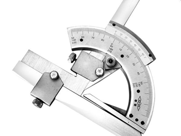
The protractor is equipped with a vernier scale featuring 5-minute graduations, allowing precise readings down to small angular units. An integrated magnifying lens provides enhanced visibility of the intersection point between the main and vernier scales. Additionally, a fine-adjustment knob and locking clamp secure the angle after alignment, preventing any shift during reading. The protractor allows measurements in both clockwise and counterclockwise directions, with a measuring range up to 270 degrees (3 x 90°), suitable for a wide variety of measurement scenarios in manufacturing environments.
Component Structure
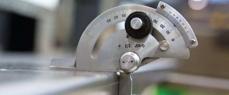
A standard universal bevel protractor set consists of the following components:
1. Thumb screw for quick fixation
2. Clamping screw to secure the measured part
3. Graduated metal blade made of stainless steel
4. Circular graduated dial attached to the main body
5. Fine-adjustment knob for precise positioning
6. Main scale disc for angle reading
7. Magnifying lens for clearer scale visibility
8. Vernier scale with fine graduations
9. Base support bar for stable positioning
10. Flat measuring surface for direct contact with the workpiece
11. Acute angle attachment for measuring hard-to-reach internal angles
12. Extension bar for compatibility with height gauges
13. Accessory clamp for mounting the protractor onto a base
Each component plays a specific role in the measurement process. Understanding the structure ensures more accurate operation and helps prolong the device’s service life.
Conclusion:
Using the universal bevel protractor is not overly complex if the operating principle and proper procedures are well understood. It is an essential tool in work environments that demand high geometric accuracy.