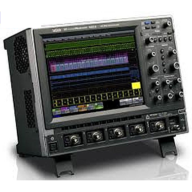
Lecroy WaveRunner 44MXi-A Oscilloscope (400Mhz, 4CH, 5GS/s)
Manufacturer: LECROY Model: 44MXi-A - Contact
Call for the best price
Hanoi city: (024) 35.381.269
Danang city: (023) 63.747.711
Bac Ninh city: (0222)730.39.68
HCM city: (028) 38.119.636
Analog Bandwidth:400 MHz
Single-Shot Sample Rate/Ch:5GS/s
Input Channels:4
Color 10.4" flat-panel TFT-LCD with high resolution touch screen
Includes Advanced Math, Customization Package, Jitter and Timing Analysis, and HDTV Trigger (XMATH, XDEV, JTA2, HDTV-TRIG)
- Datasheet
- Specification
- Videos & Demos
- Software & Utilities
- Firmware
- Manuals
- Programming Examples
- Application Notes
- Request Demo
The Teledyne LeCroy WaveRunner Xi-A is the most powerful and capable scope available in its class. Basic system validation using advanced triggers, fast viewing modes, measurement parameters, or serial decodes is simple and easy. Advanced debug, multi-domain analysis, and waveshape analysis are possible with tools unique to WaveRunner Xi-A. Optional application packages help you make sense of well-defined problems.
 Trigger on I2C, SPI, UART, RS-232, AudioBus (I2S, LJ, RJ, TDM), LIN, CAN, or FlexRay or MIL-STD-1553 serial data patterns. Intuitively decode values on the oscilloscope grid.
 An extensive collection of SMART, Serial, and Digital (MS Series) triggers enables users to quickly and easily isolate events of interest (some optional).
 Use the high sampling rate and WaveStream fast viewing mode to characterize signal shape, rise time, overshoot, etc., and verify the presence or absence of high-speed transients.
 Sequence Mode allows you to partition your acquisition memory into segments and capture specific events over long periods of time. Then, view and analyze each segment individually.
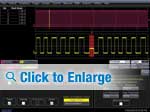 Search and Analysis WaveScan provides the ability to locate unusual events in a single capture, or scan for an event in many acquisitions over a long period of time using more than 20 different search/scan modes. Use ScanHisto or ScanOverlay to display intuitive scanned results.
Quickly create your own measurement parameters or math functions using Excel, MATLAB®, or VBScripts (some capability optional).
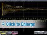 Use a variety of application packages to provide detailed, fast solutions for specific problems.
WaveRunner Xi-As long memory is optimized for calculation of more information 10–100x faster than other oscilloscopes, while enabling easy access to simple zooming and positioning from the front panel.
More standard and optional measurements and more powerful math capability are provided with results returned faster than in other oscilloscopes.
 Amplify your understanding with multidomain analysis of your signals. Convert signal information into Statistical domain (Histogram), Spectral domain (long memory FFTs), Jitter, Modulation, or other Measurement Parameter domains (Tracks of measurement parameters). (Some capability is optional.)
 Teledyne LeCroy math, measure, and analysis tools are tightly integrated with basic scope operations. Its easy to link capabilities and expand understanding. Free yourself from constraints!
A wide variety of active FET probes, current probes, differential probes, HV probes, etc. with complete tip and ground accessories make it easy to probe your signals.
The MS Series can capture digital signals with speeds up to 500 MHz. View up to 36 digital channels with up to 50 Mpts/Ch memory and analyze analog and digital events together.
Excellent overdrive recovery and signal integrity make WaveRunner Xi-A ideal for high-voltage switching loss, conduction loss, ripple, switching power supply, and other amplifier measurements. Use with Teledyne LeCroy Differential Amplifiers for highperformance 100,000:1 Common Mode Rejection Ratio.
Extensive triggers allow fast event isolation. Measure timing statistically and view behavior graphically using histograms. Gain real understanding of root cause.
Long memory, HFREJ trigger coupling, built-in noise filtering, etc. enable fast understanding of signal behavior in circuits with a mix of slow-speed (sensor, actuator, power supply, mechanical) and high-speed signals.
Vertical System |
|
| Nominal Analog Bandwidth @ Ω 50 10 mV-1 V/div | 400 MHz |
| Rise Time (typical) | 875 ps |
| Input Connector | ProBus/BNC |
| Input Channels | 4 |
| Bandwidth Limiters | 20 MHz; 200 MHz |
| Input Impedance | 1 MΩ || 16 pF or 50 Ω |
| Input Coupling | 50 Ω: DC, 1 MΩ: AC, DC, GND |
| Maximum Input Voltage | 50 Ω: 5 Vrms, 1 MΩ: 400 V max. (DC + Peak AC = 5 kHz) |
| Vertical Resolution | 8 bits; up to 11 with enhanced resolution (ERES) |
| Sensitivity | 50 Ω: 2 mV/div–1 V/div fully variable; 1 MΩ: 2 mV–10 V/div fully variable |
| Offset Range | 50 Ω: ±1 V @ 2–98 mV/div, ±10 V @ 100 mV/div–1 V/div; 50 Ω: 1 M Ω: ±1 V @ 2–98 mV/div, ±10 V @ 100 mV/div–1 V/div, ±100 V @ 1.02 V/div–10 V/div |
Main Specifications |
|
| Probes | One PP008 per channel standard; Optional passive and active probes available. |
Timebase System |
|
| Roll Mode | User selectable at <= 500 ms/div and <= 100 kS/s |
Horizontal System |
|
| Timebases | Internal timebase common to all input channels; an external clock may be applied at the auxiliary input |
| Time/Division Range | Real time: 200 ps/div–10 s/div, RIS mode: 200 ps/div to 10 ns/div, Roll mode: up to 1,000 s/div |
| Clock Accuracy | <= 5 ppm @ 25 °C (typical) (<= 10 ppm @ 5–40 °C) |
| Sample Rate and Delay Time Accuracy | Equal to Clock Accuracy |
| Trigger and Interpolator Jitter | Jitter <=3 ps rms (typical) |
| Channel-Channel Deskew Range | ±9 x time/div setting, 100 ms max., each channel |
| External Clock | DC to 600 MHz; (DC to 1 GHz for 104Xi and 204Xi) 50 Ω, (limited BW in 1 MΩ), BNC input, limited to 2 Ch operation (1 Ch in 62Xi-A), (minimum rise time and amplitude requirements apply at low frequencies) |
Acquisition System |
|
| Single-Shot Sample Rate/Ch | 5 GS/s |
| Random Interleaved Sampling (RIS) | 200 GS/s |
| Maximum Trigger Rate | 1,250,000 waveforms/second |
| Interleaved Sample Rate (2 Ch) | 5 GS/s |
| RIS Mode | User selectable from 200 ps/div to 10 ns/div |
| Acquisition Memory Options | Max. Acquisition Points (4 Ch/2 Ch, 2 Ch/1 Ch in 62Xi-A) Segments (Sequence Mode) |
| Sequence Time Stamp Resolution | 1 ns |
| Standard Memory | 12.5M/25M 10,000 |
Acquisition Processing |
|
| Averaging | Summed and continuous averaging to 1 million sweeps |
| Enhanced Resolution (ERES) | From 8.5 to 11 bits vertical resolution |
| Envelope (Extrema) | Envelope, floor, or roof for up to 1 million sweeps |
| Interpolation | Linear or (Sinx)/x |
| Time Resolution (min, Single-shot) | 200 ps (5 GS/s) |
Triggering System |
|
| Trigger Modes | Normal, Auto, Single, Stop |
| Sources | Any input channel, External, Ext/10, or Line; slope and level unique to each source, except Line |
| Coupling | DC, AC (typically 7.5 Hz), HF Reject, LF Reject |
| Pre-trigger Delay | 0–100% of memory size (adjustable in 1% increments, or 100 ns) |
| Post-trigger Delay | Up to 10,000 divisions in real time mode, limited at slower time/div settings in roll mode |
| Hold-off by Time or Events | 1 ns to 20 s or 1 to 1,000,000,000 events |
| Internal Trigger Range | ±4.1 div from center (typical) |
| Trigger Sensitivity with Edge Trigger (Ch 1–4) | 2 div @ < 400 MHz 1 div @ < 200 MHz |
| Max. Trigger Frequency, SMART Trigger | 400 MHz @ = 10 mV |
| External Trigger Input Range | EXT/10 ±4 V; EXT ±400 mV |
| Minimum Time Between Sequential Segments Sequential Segments | 800 ns |
Basic Triggers |
|
| Edge | Triggers when signal meets slope (positive, negative, or Window) and level condition. |
| TV-Composite Video | Triggers selectable fields (1, 2, 4, or 8), Positive or Negative slope, or Line (up to 1500), for NTSC, PAL, SECAM, or non-standard video (up to 1500 lines). |
SMART Triggers |
|
| State or Edge Qualified | Triggers on any input source only if a defined state or edge occurred on another input source. Delay between sources is selectable by time or events. |
| Dropout | Triggers if signal drops out for longer than selected time between 1 ns and 20 s. |
| Pattern | Logic combination (AND, NAND, OR, NOR) of 5 inputs (4 channels and external trigger input – 2 Ch+EXT on WaveRunner 62Xi-A). Each source can be high, low, or don’t care. The High and Low level can be selected independently. Triggers at start or end of the pa |
SMART Triggers with Exclusion Technology |
|
| Glitch and Pulse Width | Triggers on positive or negative glitches with widths selectable from 500 ps to 20 s or on intermittent faults (subject to bandwidth limit of oscilloscope). |
| Signal or Pattern Interval | Triggers on intervals selectable between 1 ns and 20 s. |
| Timeout (State/Edge Qualified) | Triggers on any source if a given state (or transition edge) has occurred on another source. Delay between sources is 1 ns to 20 s, or 1 to 99,999,999 events. |
| Runt | Trigger on positive or negative runts defined by two voltage limits and two time limits. Select between 1 ns and 20 s. |
| Slew Rate | Trigger on edge rates. Select limits for dV, dt, and slope. Select edge limits between 1 ns and 20 s. |
| Exclusion Triggering | Trigger on intermittent faults by specifying the normal width or period. |
Color Waveform Display |
|
| Type | Color 10.4" flat-panel TFT-LCD with high resolution touch screen |
| Resolution | SVGA; 800 x 600 pixels; maximum external monitor output resolution of 2048 x 1536 pixels |
| Number of traces | Display a maximum of 8 traces. Simultaneously display channel, zoom, memory, and math traces. |
| Grid Styles | Auto, Single, Dual, Quad, Octal, XY, Single + XY, Dual + XY |
| Waveform Representation | Sample dots joined or dots only in real-time mode |
Internal Waveform Memory |
|
| Internal Waveform Memory | M1, M2, M3, M4 Internal Waveform Memory (store full-length waveform with 16 bits/data point) or store to any number of files limited only by data storage media. |
LeCroy WaveStream™ Fast Viewing Mode |
|
| Intensity | 256 Intensity Levels, 1–100% adjustable via front panel control |
| Number of Channels | up to 4 simultaneously |
| Max Sampling Rate | 5 GS/s |
| Waveforms | up to 8000 waveforms/second |
| Operation | Front panel toggle between normal real-time mode and LeCroy WaveStream Fast Viewing mode |
Setup and Waveform Storage |
|
| Front Panel and Instrument Status | Store to the internal hard drive, over the network, or to a USB-connected peripheral device. |
Zoom Expansion Traces |
|
| Zoom Expansion Traces | Display up to 4 Zoom/Math traces with 16 bits/data point |
Interface |
|
| Remote Control | Via Windows Automation, or via LeCroy Remote Command Set |
| GPIB Port (optional) | Supports IEEE – 488.2 |
| Ethernet Port | 10/100/1000Base-T Ethernet interface (RJ-45 connector) |
| USB (Host) | 5 USB 2.0 ports (one on front of instrument) supports Windows-compatible devices. |
| External Monitor Port | Standard 15-pin D-Type SVGA-compatible DB-15; connect a second monitor to use extended desktop display mode with XGA resolution. |
| Serial Port | DB-9 RS-232 port (not for remote oscilloscope control) |
Auxiliary Input |
|
| Signal Types | Selected from External Trigger or External Clock input on front panel |
| Coupling | 50 Ω: DC, 1 MΩ: AC, DC, GND |
| Maximum Input Voltage | 50 Ω: 5 Vrms, 1 MΩ: 400 V max. (DC + Peak AC = 5 kHz) |
Auxiliary Output |
|
| Signal Types | Trigger Enabled, Trigger Output. Pass/Fail, or Off |
| Output Signal | TTL, ˜3.3 V |
| Calibrator Signal | Output available on front panel connector provides a variety of signals for probe calibration and compensation. |
Automatic Setup |
|
| Auto Setup | Automatically sets timebase, trigger, and sensitivity to display a wide range of repetitive signals. |
| Vertical Find Scale | Automatically sets the vertical sensitivity and offset for the selected channels to display a waveform with maximum dynamic range. |
General |
|
| Auto Calibration | Ensures specified DC and timing accuracy is maintained for 1 year minimum. |
| Power Requirements | 90–264 Vrms at 50/60 Hz; 115 Vrms (±10%) at 400 Hz, Automatic AC Voltage Selection Installation Category: 300V CAT II; Max. Power Consumption: 340 VA/340 W; 290 VA/290 W for WaveRunner 62Xi-A |
Probes |
|
| Probe System: ProBus | Automatically detects and supports a variety of compatible probes. |
| Scale Factors | Automatically or manually selected, depending on probe used |
Environmental and Safety |
|
| Temperature (Operating) | +5 °C to +40 °C |
| Temperature (Non-Operating) | -20 °C to +60 °C |
| Humidity (Operating) | Maximum relative humidity 80% for temperatures up to 31 °C decreasing linearly to 50% relative humidity at 40 °C |
| Humidity (Non-Operating) | 5% to 95% RH (non-condensing) as tested per MIL-PRF-28800F |
| Altitude (Operating) | Operating Up to 2,000 m |
| Altitude (Non-Operating) | Non-Operating 12,190 m |
Physical Dimensions |
|
| Dimensions (HWD) | 260 mm x 340 mm x 152 mm Excluding accessories and projections (10.25" x 13.4" x 6") |
| Net Weight | 6.95 kg. (15.5 lbs.) |
Certifications |
|
| Certifications | CE Compliant, UL and cUL listed; Conforms to EN 61326, EN 61010-1, UL 61010-1 2nd Edition, and CSA C22.2 No. 61010-1-04. |
OPTION
Serial Data Compliance |
| QPHY-ENET QualiPHY Enabled Ethernet 10/100/1000BT Compliance Software Option |
| QPHY-USB QualiPHY Enabled USB 2.0 Compliance Software Option |
| ENET-2ADA-BNCSMA Adapter Set- 2 BNC/M to SMA/F |
| ENET-2CAB-SMA018 Cable Set- 2 SMA-SMA 18 inches |
| ENET-2CAB-SMA036 Cable Set- 2 SMA-SMA 36 inches |
| ET-PMT Electrical Telecom Pulse Mask Software; |
| WRXi-SDM Serial Data Mask Software Package for WaveRunner Xi Series |
Serial Trigger and Decode |
| WRXi-USB2-HSICbus D USB 2.0 HSIC Decode Option |
| CANbus TD CANbus TD Trigger and Decode Option |
| CANbus TDM CAN Bus Trigger, Decode, and Measure/Graph option |
| WRXi-DigRFV4bus D DigRF V4 Bus Decode option for WaveRunner Xi series |
| CANbus TD 5LIC CAN Bus Trigger and Decoding Package with License to work on 5 oscilloscopes |
| WRXi-NRZbus D NRZ Bus Decode Option for WaveRunner Xi |
| WRXi-Manchesterbus D Manchester Bus Decode Option for WaveRunner Xi |
| WRXi-ENETbus D ENET Bus Decode Option for WaveRunner Xi |
| CANbus TDM-5LIC CAN Bus Trigger, Decode, and Measure/Graph option with 1 Hardware Kit and 5 SW Licenses |
| TC1041-OPTO CAN 1041 Opto-isolated High-speed Trigger Coupler |
| TC1050-OPTO CAN 1050 Opto-isolated High-speed Trigger Coupler |
| TC1054-OPTO CAN 1054 Opto-isolated Low-speed Trigger Coupler |
| TC251-OPTO CAN 251 Opto-isolated High-speed Trigger Coupler (one is included with CANbus TD) |
| TC5790c-OPTO CAN 5790c Opto-isolated Single-wire Trigger Coupler |
| TC10011-OPTO CAN B10011S Opto-isolated Truck and Bus Trigger Coupler |
| WRXi-MSO-EMB Embedded bundle, Includes MS-500-36 with I2C TD, SPI TD, UART TD |
| WRXI-EMB Embedded bundle, Includes I2C TD, SPI TD, UART TD |
| WRXi-1553 TD MIL-STD-1553 Trigger and decode option for WaveRunner Xi |
| WRXi-ARINC429bus DSymbolic ARINC 429 Bus Symbolic Decode option for WaveRunner Xi/Xi-A |
| WRXi-AudioBus TD AudioBus trigger and decode for WaveRunner Xi |
| WRXi-AudioBus TDG AudioBus trigger, decode, and graph for WaveRunner Xi |
| WRXi-CANbus TD CAN Bus Trigger and Decode Option |
| WRXi-CANbus TDM CAN Bus Trigger Decode and Measure/Graph Option |
| WRXi-DigRF3Gbus D DigRF 3G Bus Decode option for WaveRunner Xi/Xi-A |
| WRXi-DPHYbus D D-PHY Bus Decode option for WaveRuner Xi/Xi-A |
| WRXI-FLEXRAYBUS TD FlexRay Trigger and Decode Option |
| WRXi-FlexRaybus TDP FlexRay Trigger, Decode and Physical Layer Test Option |
| WRXI-I2CBUS TD I2C Bus Trigger & Decode Option for WaveRunner Xi Oscilloscopes |
| WRXI-LINBUS TD LIN Bus Trigger & Decode Option for WaveRunner Xi Series Oscilloscopes |
| WRXi-PROTObus MAG Serial Debug Toolkit - Measure Analyze Graph for WaveRunner Xi/Xi-ACompatible with I2C, SPI, UART, CAN, LIN, FLX, D-PHY, DigRF 3G, DigRF v4, ARINC 429, MIL-STD-1553 |
| WRXi-ProtoSync Decode Annotation and Protocol Analyzer Software Synchronization Option for WaveRunner Xi/Xi-ACompatible with USB2bus D, SATAbus D, SASbus D, FCbus D |
| WRXi-SATAbus D SATA Decode option for WaveRunner Xi/Xi-ASupports SATA Gen 1, 2, and 3. |
| WRXI-SPIBUS TD SPI Bus Trigger & Decode Option for WaveRunner Xi Oscilloscopes |
| WRXi-UART-RS232BUS TD UART and RS232 Bus Trigger and Decode Option for WaveRunner Xi Oscilloscopes |
| WRXi-USB2bus D USB 2.0 Bus Decode option for WaveRunner Xi/Xi-A |
| WRXI-SENTbus D SENT Bus Decode Option for WaveRunner Xi |
Jitter Analysis Software |
| WRXi-JITKIT Clock, clock-data Jitter Analysis and views of time, statistical, spectral, and jitter overlay |
Miscellaneous |
| WRXi-SOFTCASE WRXi Soft Carrying Case |
| WRXi-HARDCASE WRXi Hard Carrying Case |
| WRXi-KYBD WRXi Keyboard Accessory |
| WRXi-RACK WRXi Rack Mount Accessory Kit |
| WRXi-MS-CLAMP WRXi Clamp Mounting Stand |
| WRXi-A-FP-GERMAN WRXi-A German Front Panel Overlay |
| WRXi-A-FP-FRENCH WRXi-A French Front Panel Overlay |
| WRXi-A-FP-ITALIAN WRXi-A Italian Front Panel Overlay |
| WRXi-A-FP-SPANISH WRXi-A Spanish Front Panel Overlay |
| WRXi-A-FP-JAPANESE WRXi-A Japanese Front Panel Overlay |
| WRXi-A-FP-KOREAN WRXi-A Korean Front Panel Overlay |
| WRXi-A-FP-CHNES-TR WRXi-A Chinese (Traditional) Front Panel Overlay |
| WRXi-A-FP-CHNES-SI WRXi-A Chinese (Simplified) Front Panel Overlay |
| WRXi-A-FP-RUSSIAN WRXi-A Russian Front Panel Overlay |
Other Software Options |
| WRXi-SPECTRUM Spectrum Analyzer and Advanced FFT Option for WaveRunner Xi Series |
| WRXi-EMC EMC Pulse Parameter Package |
| WRXi-STAT Histogram and Statistical Analysis Pkg. |
| WRXi-XDEV Advanced Customization Software Package for WaveRunner Xi Series |
Data Storage Software |
| WRXi-AORM Advanced Options Record Measurement Package |
| WRXi-DDM2 Disk Drive Measurement Software Package for WaveRunner Xi Series |
Remote Control/Network Options |
| USB2-GPIB External USB 2.0 to GPIB IEEE 488.2 adapter |
Power Analysis Software |
| WRXi-PWR Power Analysis Option for WR Xi |
Digital Filtering Software |
| WRXi-DFP2 Digital Filter Software Package for WaveRunner Xi Series |
Mixed Signal Solutions |
| MS-500 500 MHz, 18 Channels, 2 GS/s, 50 Mpts/ch Mixed Signal Oscilloscope Option |
| MS-500-36 250 MHz,36 Ch,1 GS/s,25 Mpts/ch (500MHz,18 Ch,2 GS/s,50 Mpts/ch Interleaved) Mixed Signal Option |
| MS-250 250 MHz, 18 Channels, 1 GS/s, 10 Mpts/ch Mixed Signal Oscilloscope Option |
Mixed Signal Accessories |
| PK400-1 Large Gripper Probe Set for 0.10 inch (2.54mm) pin pitch. Includes 10 probes with color coded leads |
| PK400-2 Medium Gripper Probe Set for 0.04 inch (1.0mm) pin pitch. Includes 10 probes with color coded leads |
| PK400-3 Small Gripper Probe Set for 0.008 inch (0.2 mm) pin pitch. Includes 10 probes with color coded leads |
| MSO-MICTOR 36 Channel Mictor Connector for MS Series (Includes 1 MSO-MICTOR-SHROUD) |
| MSO-3M 18 Pin 3M Interface cable MSO-3M (Mates with 3M part number 2520-6002) |
| MSO-DLS-36 16" Digital Lead Set, D18-D35 |
| MSO-MICTOR-SHROUD Shroud for MSO-MICTOR connector, Kit of 3 |
Serial Data Test Fixtures |
| TF-ENET-B 10/100/1000BaseT Ethernet Test Fixture |
| TF-USB-B USB 2.0 Compliance Test Fixture |
- Quality Engagement
- Easy change and return
- Delivery Avaliable
- Favorable payment