Coupler
In RF signal chains, precise control of how power is sampled, split, or monitored can make a major difference in measurement quality and system stability. Whether you are building a microwave test setup, integrating signal distribution hardware, or refining a high-frequency subsystem, choosing the right Coupler helps you manage signal flow with better consistency and lower uncertainty.
This category brings together couplers used in RF and microwave applications where directional behavior, insertion loss, isolation characteristics, and frequency coverage all matter. For engineers, buyers, and system integrators, the goal is usually not just to find a compatible part, but to select a component that fits the wider architecture of the circuit, test bench, or communication path.
Where couplers fit in RF and microwave systems
A coupler is commonly used to sample a portion of RF energy from a transmission line while allowing the main signal to continue through the primary path. This makes it useful in applications such as power monitoring, reflection measurement, signal leveling, and test instrumentation, especially where non-intrusive signal access is important.
In practical terms, couplers often appear in lab environments, production testing, antenna systems, microwave links, and high-frequency development platforms. Compared with other RF building blocks, a coupler is selected less by appearance and more by electrical behavior across the intended band, including coupling value, directivity, return loss, and power handling. If you are comparing broader device types, it can also help to review related RF multiplexer options for signal routing tasks with different design goals.
Key parameters to evaluate before selecting a coupler
The first selection factor is usually the frequency range. A coupler that performs well at lower RF frequencies may not be suitable in microwave or millimeter-wave environments, where tolerances become tighter and waveguide structures may be preferred. Engineers typically begin by matching the usable band to the operating range of the overall system.
The next important consideration is coupling level, expressed in dB. This indicates how much of the mainline signal is extracted for monitoring or measurement. Higher coupling values mean a smaller sampled signal, which can be useful when the main path carries substantial power and the coupled port is intended only for sensing.
Other practical parameters include insertion loss on the mainline, directivity, impedance, VSWR, connector style, and continuous or peak power capability. In many RF test and measurement environments, these characteristics must be considered together rather than individually, because the wrong tradeoff in one area can reduce overall system accuracy.
Directional, waveguide, and application-specific designs
Not all couplers serve the same purpose. A directional coupler is designed to distinguish forward and reverse traveling power, which is essential for tasks such as reflected power analysis, matching verification, and protection of sensitive RF equipment. This behavior is especially relevant in microwave systems where signal integrity and mismatch effects need to be closely monitored.
In higher-frequency bands, waveguide couplers become especially relevant. These designs are built for waveguide transmission structures rather than standard coaxial interconnects, making them suitable for applications where low loss, high-frequency performance, and power handling are priorities. Buyers working in these bands should pay close attention to waveguide type, interface compatibility, and the intended physical integration of the component.
Example from the current product range
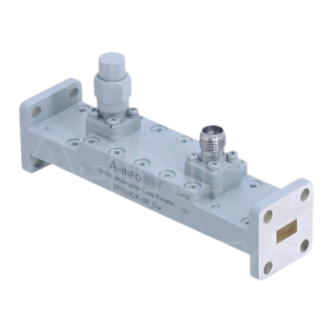
One representative product in this category is the A-INFOMW 28WHCK-60_Cu waveguide loop coupler, covering 26.5 GHz to 40 GHz in the Ka band. Based on the available data, it is a directional loop coupler built around a WR28 rectangular waveguide format, which makes it relevant for microwave and millimeter-wave setups where compact waveguide integration and controlled sampling are required.
Its published characteristics indicate a 60 dB coupling level, low typical insertion loss, and defined power handling for both continuous and peak conditions. Those specifications suggest a role in measurement-oriented applications where only a small portion of the signal must be extracted while preserving the main transmission path. For users seeking more components from this supplier, the A-INFOMW brand page is a useful starting point.
How to compare manufacturers in this category
Different manufacturers may focus on different parts of the RF and microwave landscape. Some are better known for broadband coaxial solutions, while others may offer stronger coverage in precision microwave assemblies, EMC-related accessories, or specialized test components. Within this category, brands such as Fairviewmicrowave, KRYTAR, A-INFOMW, Schwarzbeck, and Tekbox provide useful reference points depending on the target application and frequency domain.
When comparing suppliers, it is often more helpful to evaluate portfolio fit than to focus on brand name alone. Consider whether the manufacturer supports the relevant frequency band, mechanical interface, signal direction requirements, and test environment. In engineering procurement, the right part is usually the one that reduces integration risk and aligns cleanly with the rest of the RF chain.
Couplers within a broader RF component ecosystem
Couplers are rarely selected in isolation. They are usually part of a wider subsystem that may include shielding, modulation stages, detection functions, or additional signal-conditioning hardware. For example, a coupler may sit upstream of monitoring circuitry, near filtering stages, or alongside protection and packaging measures intended to maintain repeatable RF behavior.
If your design also involves enclosure-level noise control or EMI management, related RF shielding components may also be relevant. In phase-sensitive designs, signal timing and phase alignment can become part of the selection process as well, especially when the coupler is integrated into calibration, feedback, or measurement loops.
Practical buying considerations for engineers and B2B procurement teams
For technical buyers, the best selection process starts with the application rather than the catalog. Define the operating frequency, expected power level, system impedance, interface format, and whether the coupled signal is intended for measurement, feedback, protection, or distribution. Once those conditions are clear, narrowing the available options becomes much easier.
It is also wise to review installation constraints such as connector orientation, waveguide standard, available mounting space, and compatibility with existing test equipment. In B2B environments, procurement teams often benefit from coordinating early with design engineers so that electrical and mechanical requirements are captured before ordering. That approach helps avoid component mismatch, redesign delays, and avoidable qualification work.
Choosing the right coupler for your RF application
This category is intended for users who need dependable RF and microwave coupling components for signal monitoring, measurement, and controlled power extraction. From directional designs to waveguide-based solutions in higher-frequency bands, the right choice depends on how the component performs inside the full signal path, not just on a single headline specification.
By reviewing the operating band, coupling value, physical interface, and system role together, you can shortlist couplers that are technically appropriate and easier to integrate. If your project spans multiple RF functions, it is worth exploring adjacent categories and relevant manufacturers to build a more complete and compatible solution set.
Get exclusive volume discounts, bulk pricing updates, and new product alerts delivered directly to your inbox.
By subscribing, you agree to our Terms of Service and Privacy Policy.
Direct access to our certified experts